iv
Curtis 1204M/05M/09M/21M Manual
FIGURES
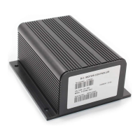
fig. 1: Curtis 1204M and 1209M electronic motor controllers ............1
fig. 2: Mounting dimensions, Curtis 1204M/05M controllers ............3
fig. 3: Mounting dimensions, Curtis 1209M/21M controllers .............4
fig. 4: Standard wiring configuration, with active main driver .............7
fig. 5: Standard wiring configuration, with active reverse input ..........8
fig. 6: Wiring to inhibit plug braking .................................................9
fig. 7: Wiring for mechanical reversing ..............................................10
fig. 8: Wiring for Type 0 throttles .....................................................10
fig. 9: Wiring for Type 1, 3, 4, and 5 throttles .................................11
fig. 10: Wiring for Type 2 throttles ....................................................13
fig. 11: Wiring configuration for pump applications ..........................14
fig. 12: Effect of throttle adjustment parameters ..................................22
TABLES
table 1: High current connections .....................................................5
table 2: Low current connections ......................................................5
table 3: J4 connector pinout .............................................................6
table 4: Status LED fault codes .......................................................26
table 5: Troubleshooting chart ........................................................28
FIGURES / TABLES