Curtis PMC 1204X/1205X/1209/1221 Manual
33
TROUBLESHOOTING & BENCH TESTING
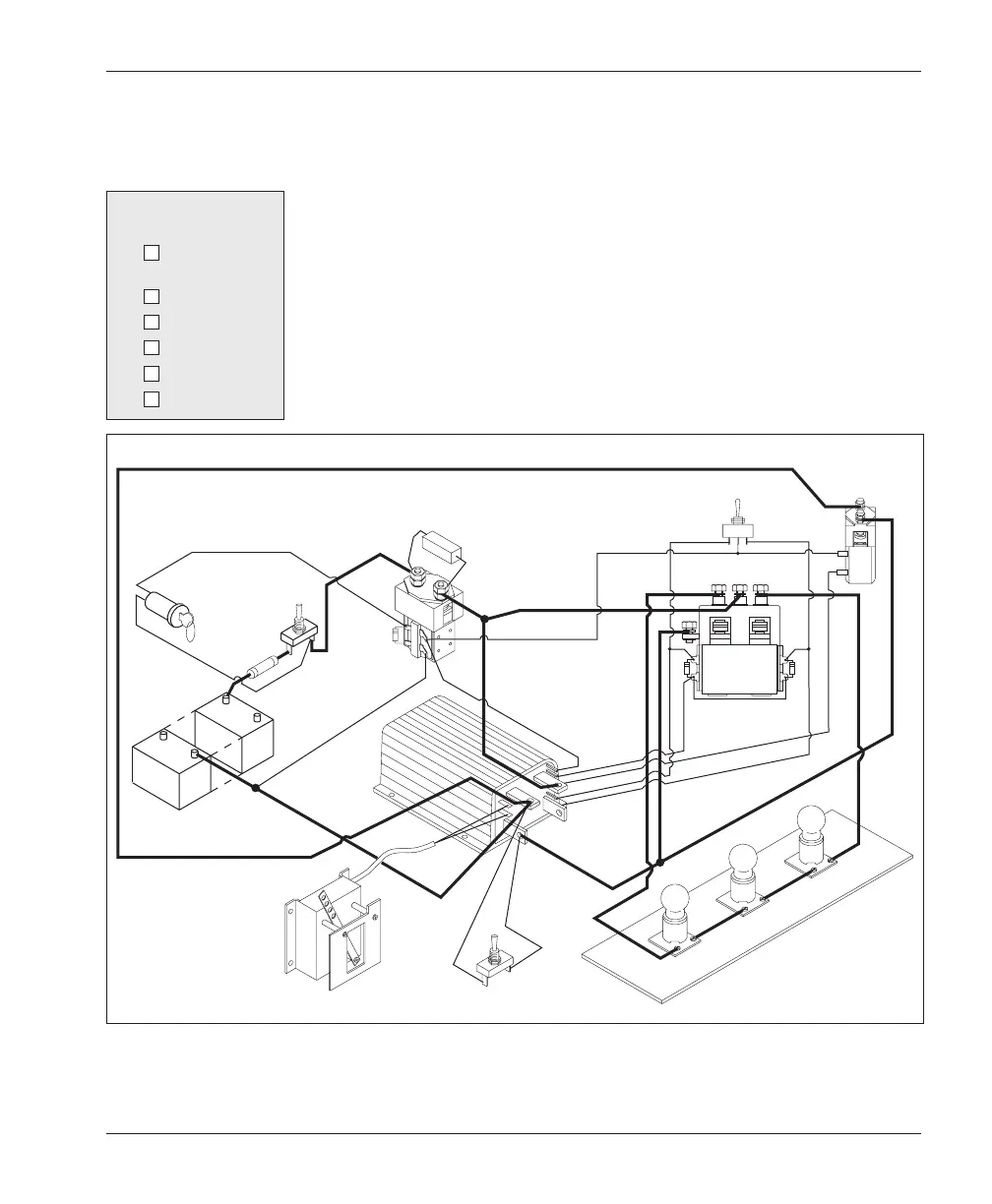
Fig. 18 Setup for bench testing.
F/R SWITCH
F/R CONTACTOR
BYPASS
CONTACTOR
FORWARD
REVERSE
POWER SUPPLY
(to match your controller)
POTBOX
(to match your controller’s
throttle output)
TEST LOAD
(to match battery voltage)
MAIN
CONTACTOR
POWER
SWITCH
KEYSWITCH
FWD
REV
FAULT
SWITCH
10A FUSE
FWD input
12V
12V
12V
5W, 250
Ω
RESISTOR
R
E
V
input
B
ypass contactor output
F/R
output
K
SI
Pin detail for Fig. 18
P1 ■ —KSI input
P2 ■ —F/R output
P3 ■—Bypass output
P4 ■ (n/c)
P5 ■ —FWD input
P6 ■ —REV input
• FORWARD/REVERSE CONTACTORS and a single-pole,
center-off FORWARD/REVERSE SWITCH.
• a BYPASS CONTACTOR if one is used in the vehicle.
• a TEST LOAD consisting of incandescent light bulbs wired in
series to get the same voltage as your power supply. (For example,
with a 36 volt battery, use three 12 volt bulbs.)
• a FAULT SWITCH (a simple on/off switch) to simulate a fault
condition.
• a general purpose VOLT OHMMETER or DIGITAL VOLT-
METER.
 Loading...


