Curtis PMC 1204X/1205X/1209/1221 Manual
48
APPENDIX B
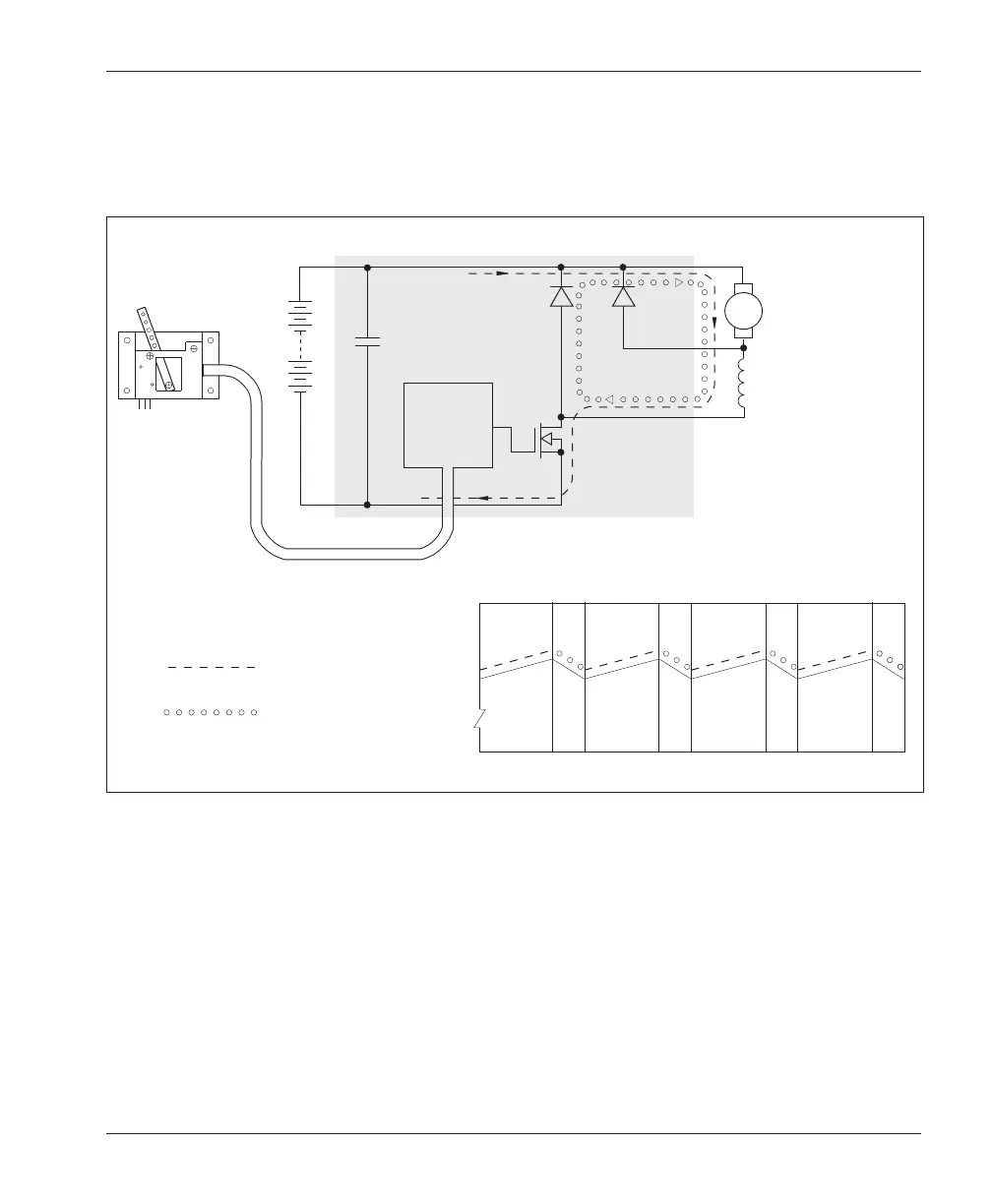
PULSE WIDTH MODULATION
A high power semiconductor switch, consisting of an array of parallel power MOSFET transistors, controls
the current in the motor windings. The transistors are connected in series with the battery and the motor. The
transistors are turned on and off 15,000 times per second by the controller circuitry, while the ratio of the on/
off times is varied in response to the input demanded by the throttle.
When the transistors are on, the current through the motor builds up, storing energy in the motor’s magnetic
field. When the transistors are off, the stored energy causes the motor current to continue to flow through the
freewheel diode. The control current ramps up and down as the switch turns on and off. Average current,
which determines motor torque, is controlled by the ratio of on/off times. Smooth, stepless control of the
power delivered to the motor is achieved with almost no power loss in the control components.
Fig. B-1 Pulse width modulation.
+
–
+
THROTTLE
POTBOX
FILTER
CAPS
POWER
MOSFETS
MOTOR
FIELD
PLUG
DIODE
FREEWHEEL
DIODE
ARM
TIME
MOTOR CURRENT
CURRENT PATH DURING
TRANSISTOR
ON TIME
CURRENT PATH DURING
TRANSISTOR
OFF TIME
BATTERY
CONTROL
CIRCUITRY
(SHADED AREA REPRESENTS CONTROLLER)
B+
B-
A2
M-
APPENDIX B
B-1
 Loading...


