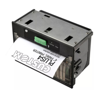
P 190
11
The J1 26-pin connector can be used if the flat cable does not exceed 700 mm in length and has a diameter
of at least 0.12 mm2. The corresponding signals are:
1 GND 2 GND
3 GND 4 TP
5 +VT 6 +VT
7 +VT 8 +VT
9 +VCC 10 +VCC
11 GND 12 GND
13 TD 14 D6
15 D5 16 D4
17 D3 18 D2
19 D1 20 D0
21 D7 * 22 RESET
23 S-EN 24 READY/RTS
25 FEED 26 STB/RD
* The D7 signal is not taken into consideration in cases of 7-bit programming of the parallel port.
In order to configure the P 190 with the extended character set, 8-bit programming of the parallel
interface is required.
The signals indicated have the following functions:
GND: signal ground and power supply;
+VT: power supply to the printer needles;
+VCC: power supply to the logic card;
S-EN (input): serial/parallel interface selection. If shortcircuited to ground (0), it enables serial
communication; if free (1) it enables parallel communication;
D0, ..., D7 (inputs): data bus. In parallel configuration, these correspond to the printer input data bus
(the high level indicates the binary digit 1). In serial communication, these are utilized to determine
speed of communication and transmission protocol; normally the data bus is at logic level 1: in order to
obtain logic level 0, it has to be shortcircuited to ground (GND).
The serial baud rate can be selected from the following table:
INSTALLATION and USE