P 190
20
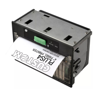
3.4 CENTRONICS PARALLEL (option)
The printer can be equipped with a CENTRONICS parallel interface to be installed on the P 190 controller.
The connection is made with a 25-pin rectangular female connector. The signal layout is exactly the
same as that used by personal computers which use the same connector, as shown in Table 3. The
pins which are not indicated are not connected.
TABLE 3
Pin Signal Direction Description:
1 STROBE IN A low level impulse on this line indicates that
there is data ready to be read by the printer
2 DATA 1 IN Data transmitted to the printer: the low level
indicates binary digit 1
3DATA 2 IN
4DATA 3 IN
5DATA 4 IN
6DATA 5 IN
7DATA 6 IN
8DATA 7 IN
9DATA 8 IN
10 ACK OUT a low level impulse indicates that the printer is
ready to receive further data
11 BUSY OUT High level active signal: indicates that the
printer cannot receive data
12 PE OUT Paper out (always to GND)
13 SELECT OUT Connection to Vcc with 4.7 ohm resistance
18 GND Pins connected to GND
19 GND
20 GND
21 GND
22 GND
23 GND
24 GND
25 GND
INTERFACE