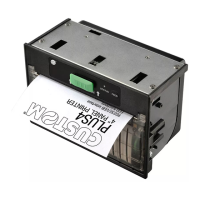
P 190
18
3.3 RS232 SERIAL (option)
The printer has an RS232 serial interface and current loop to be installed on the P 190 controller. The
connection is made with a 25-pin rectangular female connector. The signals on the connector pins are
indicated in Table 2. The pins which are not indicated are not connected. Figure 6 shows how to select
the operating modes.
TABLE 2
Pin Signal Direction To be connected to Description:
1,7 GND OUT GND Signal ground
2 TXD OUT RXD Receive Data. Serial output (from Host)
3 RXD IN TDX Transmit Data. Serial data input
(towards Host)
4 DTR OUT TXD Data Set Ready. Printer on and operating.
DCD (active at RS232 level high).
9 LOOP RD+ IN Data reception in current loop.
10 LOOP RD- - RD LOOP return.
11 LOOP RTS+ OUT Current loop:
ready to receive data.
12 LOOP RTS- - RTS LOOP return.
13 LOOP DTR+ OUT Current loop: indicates that the
printer is ON.
14 LOOP DTR- - DTR LOOP return.
15 LOOP TD+ OUT Current loop: positive level
data transmission
16 LOOP TD- - TD LOOP return
20 RTS OUT CTS Clear to Send. Ready to receive data
(active at RS232 level high)
INTERFACE