51
3 CE67 IN2
4 IN1 IN2
5 IN2 IN1
CE62 P gain 0~10.0 0 289
CE63 I gain 0.2~1000.0 sec. 1 290
CE64 Reserved 291
CE65 Output limit 0~100.0 % 100 292
CE66 PID output limit 293
CE67 PI target value Setting 0~100.0 % 100 294
CE68 PID delay time 0~10 0
295
CE69 PID offset adjust 0~200 100
296
CE70 PID output gain 0~25 1
297
CE74 P control status selection 0~1 0
301
CE77 PID delay status selection 0~1 0
302
CE78 PID output characteristic selection
0~1 1
303
CE79 PID status selection 0~4 0
304
CE80 PID target acceleration time 0~25.5 0
305
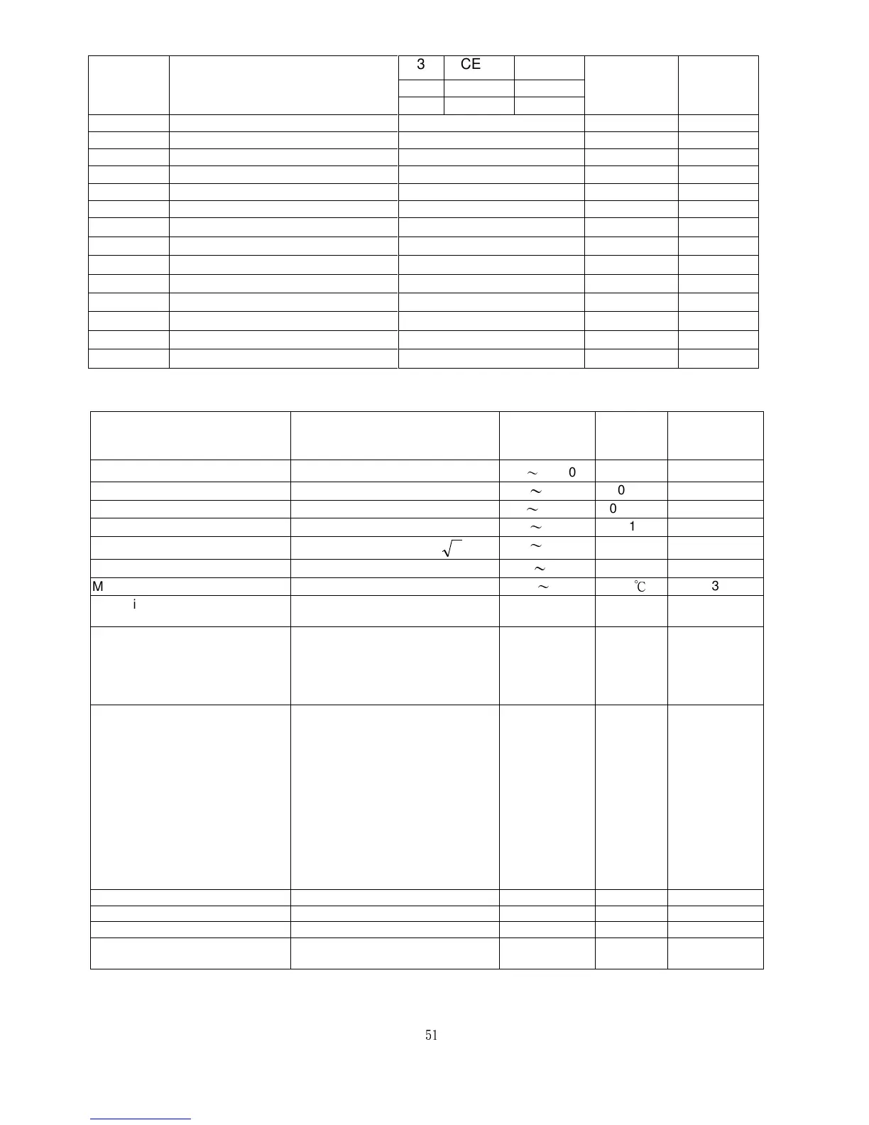
12. Modbus Address of Display Data
Description Notes
Range
Unit
MODBUS
Address
Operation frequency
0
~
24000
0.01HZ
328
Current feedback
0
~
9999
0.1A 329
Operation command
0
~
24000
0.01HZ 330
DC voltage
0
~
9999
0.1V 331
Output voltage
Vac=Output voltage /
2
0
~
9999
0.1 332
External terminal mode
0
~
255
333
Module Temperature
112
~
1130 0.1
℃
334
Operation status
Bit2: 0=Stop, 1=RUN
Bit14: 0=FR, 1=RR
335
Operation command
MASTER changes:
Bit0: FWD command
Bit1: REV command
Clear Bit0 Bit1: Stop command
Bit2: Reset after failure command