1
Introduction
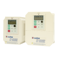
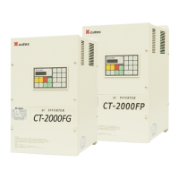
Thank you for choosing the CT-2000ES inverter unit, this inverter unit is suitable for operating squirrel cage
induction motors. Please read this instruction manual carefully before actual usage in order to ensure proper
operation and suit your needs.
Table of Contents
1. Inspection upon receiving…………………………………………………………………………………..
2. Installation and Storage……………………………………………………
…………………………..
A. Installation ……………………………………………………………………………………………..
B. Storage…………………………………………………………………………………………………
C. Outline dimension……………………………………………………………………………………..
3. Application notes……………………………………………………………………………………………..
4. Block diagram and wring …………………………………………………………………………………..
A. Wiring of main and control circuit …………………………………………………………………...
B
.
Signal circuit……………………………………………………………
………………………..
C
.
Connecting the power supply and the AC motor……………………
……………………….
D
.
R.S.T. for Power source reactor………………………………………………………………….
..
E. Brake resistor standard of usage
………………………………………………………..
F
.
Standard external connection diagram……………………………………………………….……
.
G
.
Control circuit specification…………………………………………..…………………………….
.
H
.
Terminal specifications……………………………………………………………………………..
.
5. Operation Test………………………………………………………………
………………………....
6. Adjust and Function Specification………………………………..………………………………………
..
A
.
Keypad operation……………………………………………………………………………………
11
B
.
Display specification…………………………………………………………………………………
C. Keypad specification………………………………………………………………………………..
11
D. Function Code……………………………………………………………………………………….
13
7. Description of alarm display indications …………………………………
………………………….
8. Troubleshooting………………………………………………………………………………………………
9. Maintenance and Inspection……………………………….………………………………………………
.
10. Standard Specification……………………………………………………………………………………..
A. 200V series 1 phase……………………………………………………………………….…………
B. 200V series 3 phase………………………………………………………………………………….
C. 400Vseries 3 phase…………………..………………………………………………………………
11. Function code Table……………………………………..………………………………………………
...
12. Modbus Address of Display Data….……………………………………
…………………………..
13. Series Communication User Manual..……………………………………………………………………
A. The physical link………………………………………………………………………………………
B. Data structure in communication…………………………………………………………………….
C. Function code in Modbus…………………………………………………………………………….
D. Error check generation……………………………………………………………………………….
E. Group & global broadcasting………………………………………………………………………...


