53
B. Data structure in communication
This product support MODBUS RTU and MODBUS ASCII protocol.
In ASCII mode, every byte of the data will transfer to two ASCII code.
Ex. If byte data is 63H, it will be 36H, 33H in ASCII code.
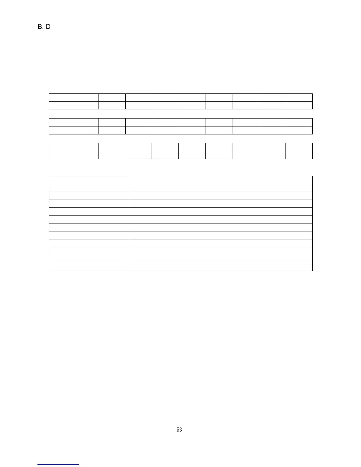
(1) Hex to ASCII code transfer table
Char ‘ 0 ’ ‘ 1 ’ ‘ 2 ’ ‘ 3 ’ ‘ 4 ’ ‘ 5 ’ ‘ 6 ’ ‘ 7 ’
ASCII code 30H 31H 32H 33H 34H 35H 36H 37H
Char ‘ 8 ’ ‘ 9 ’ ‘ A ’ ‘ B ’ ‘ C ’ ‘ D ’ ‘ E ’ ‘ F ’
ASCII code 38H 39H 41H 42H 43H 44H 45H 46H
Char ‘ : ‘ CR LF
ASCII code 3AH 0DH 0AH
(2) The data frame format explain
Field Name Explain
Header Data frame initial character
Slave Address Inverter communication address
Function Function code
Start Address Enquiry feedback data initial address
No. of Register Enquiry feedback data (word)
Byte Count Feedback data(byte)
Data Feedback data
Register Address Enquiry modified data address
Preset Data Modified data
Error Check Checksum
Trailer Data frame stop character
C. Function code in Modbus
This product supports Function code 03H and 06H in MODBUS protocol.
(1) Function 03H
:
Read holding register
Read the binary contents of holding registers (4 x references) in the slave. Broadcast is
not supported. The maximum parameters supported by various controller models are
listed on page.
Ex: Read data from 3 continuous addresses in register. The beginning address is 0080H,
the data frame are listed as follow.