4
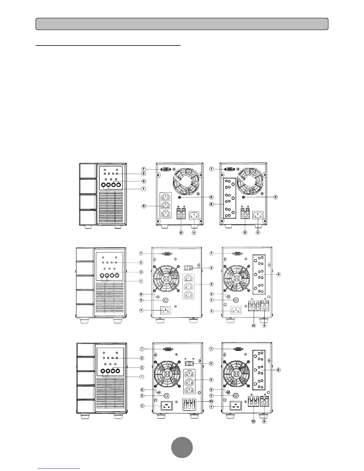
POWER MODULE FRONT/REAR PANEL DESCRIPTION
1. Power On/Off Button
Master ON/OFF for the UPS.
2. Function Buttons
Scroll up, scroll down, and silence.
3. Multifunction LED Display
Indicate status information and events.
4. AC Input Inlet
Connect the AC Power cord to a properly wired and
grounded outlet.
5. Circuit Breaker
Provide overload and fault protection.
6. Screw for XL Battery Cable with ground
Connect the XL Battery Cable and ground.
7. Serial Port
Serial port provides communication between the UPS and the
computer. The UPS can control the computer’s shutdown
during a power outage through the connection while the
computer can monitor the UPS and alter its various
programmable parameters.
8. Battery Backup & Surge Protected Outlets
Provide battery backup and surge protection. They ensure
power is provided to connected equipment over a period of time
during a power failure.
9. Extended Runtime Battery Module Connector (for
long-run models only)
Connect to additional external battery modules.
10. Output Terminal Block
Connect to your equipment.
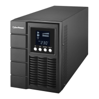
OLS1000EC/ECXL
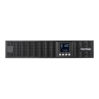
OLS2000EC/ECXL
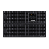
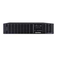
OLS3000ECXL OLS3000EC/ECXL
 Loading...