1-6 AspectFT-Matrix MAX Area Controller Installation Guide (1/05/2015)
1.3.1 POWER REQUIREMENTS
This product requires a transformer capable of providing 24VAC power to the product. Use of a UL listed
24VAC transformer is recommended.
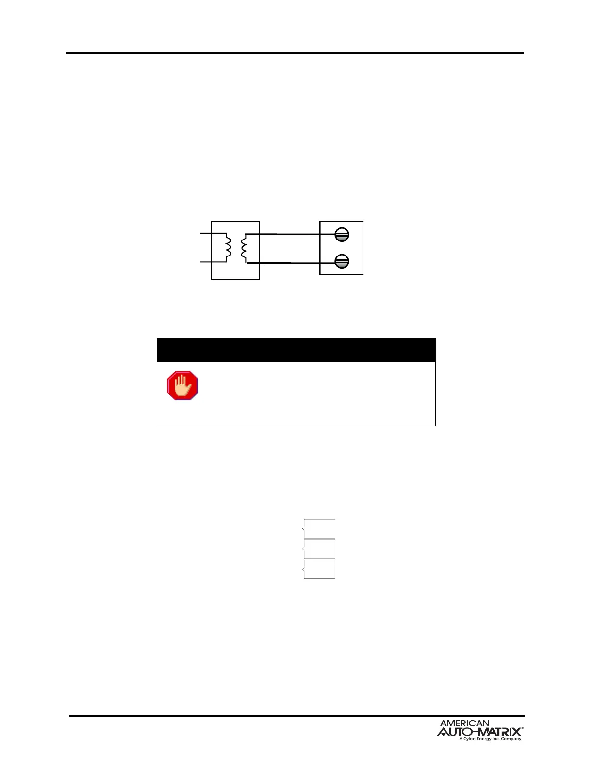
To connect power, use the supplied two-position terminal
plug. The output leads from the transformer
should be connected to the terminal plug. The terminal plug is then connected into the socket marked J1
on the PCB. American Auto-Matrix recommends using 18AWG cable for power wiring.
Figure 1-5 Connecting Power to Matrix MAX Area Controller
WARNING
Do not share the power source for AspectFT-
Matrix MAX MAX Area Controller with other
de
vices. Damage to the product as a result of
improper power and wiring will void product
warranty.
1.3.1.1 LED INDICATION
The PCB of the product includes diagnostic LEDs, providing user feedback when power has been
connected to the device. When power is connected, all three of the LEDs should be illuminated. The
power diagnostic LEDs are located near port 1’s terminal block switches.
Figure 1-6 Power LEDs on AspectFT-Matrix MAX Area Controller PCB
 Loading...