AspectFT-Matrix MAX Area Controller Installation Guide (1/05/2015) 1-7
1.4 COMMUNICATION CONNECTIONS
Communication connections should be made with care. To avoid conflicts with existing networks, it is
recommended all communication configuration of the product be performed prior to connecting physical
media from the building automation system. Refer to AspectFT-Studio On-Line Help System for additional
information.
CAUTION
It is recommended that all software configuration
be performed prior to physically connecting this
p
roduct to any associated communication
networks.
1.4.1 ETHERNET NETWORK
Ethernet is a high-speed network layer widely used in commercial buildings. This product includes an on-
board Ethernet adapter, allowing users communicate with the device for product setup, as well as for
building automation routines and applications. The Ethernet network interface is located on the single
board computer card.
The on-board Ethernet network interface supports 10Base-T (10Mbps) and 100Base-T (100Mbps)
Ethernet connec
tions. The product will automatically switch to 100Base-T operations if other devices and
cabling connected to the same subnetwork support this
1.4.1.1 CABLE TYPE AND LENGTH
Use an approved Category 5 (CAT5) Ethernet patch cable with RJ-45 plugs to connect the product to an
Ethernet switch or hub. Use professionally manufactured cables to assure reliable transmission rates and
connectivity between devices. Category 5 wiring is typically limited to about 100 meters (320 feet).
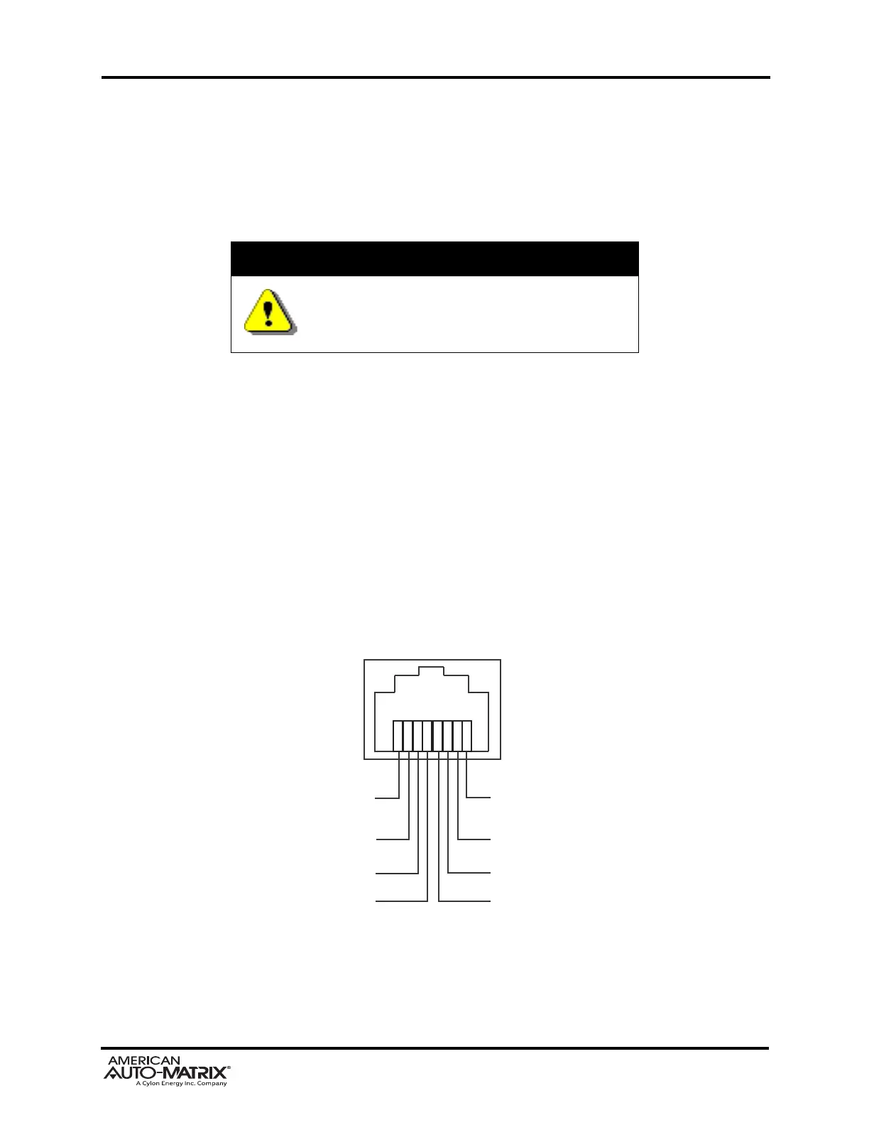
Pin 7
Reserved
Pin 8
Reserved
Pin 6
Receive -
Pin 5
Reserved
Pin 1
Transmit +
Pin 2
Transmit -
Pin 3
Receive +
Pin 4
Reserved
Figure 1-7 Standard Ethernet Connection Pinout
 Loading...