DS0119 rev 40 ©2018 Cylon All Rights Reserved. Subject to change without notice
WWW.CYLON.COM
WWW.CYLON-AUTOMATRIX.COM
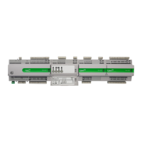
CBX System
TECHNICAL DATASHEET & INSTALLATION GUIDE
SPECIFICATIONS
MECHANICAL
Size
(excluding terminal plugs)
CBX-8R8
CBX-8R8-H
166 x 89.5 x 57 mm [6.5 x 3.55 x 2.25”]
FLX-4R4
FLX-4R4-H
FLX-8R8
FLX-8R8-H
FLX-16DI
104 x 89.5 x 57 mm [4.1 x 3.55 x 2.25”]
Flame-Retardant ABS
DIN 43880 type-2 compatible
DIN rail
CONNECTION
Note: Use Copper or Copper Clad Aluminum 70 °C conductors only.
PCB mounted plug terminal connections
)
Min: AWG 22 (0.355 mm
2
)
ENVIRONMENT
Note: This equipment is intended for field installation within an enclosure.
-25 °C … 50 °C (-13 °F … 122 °F)
0% … 90% RH non-condensing
EN 61326-1: 2013
EN 61000-3-2: 2014
EN 61000-3-3: 2013
UL Listed (CDN & US) UL916 Energy Management
Equipment – File No. E176435
ELECTRICAL
Connection Proprietary FLX bus connector carries power and
comms from CBX-8R8(-H) unit. CBX-8R8(-H) can
supply power to up to 3 FLX modules.
Power 18 V DC / 60 mA output
¼ unit load device
PROCESSOR
STM32 ARM Cortex-M3 processor
8 MHz crystal, 72 MHz internal processor clock rate
1MByte external SRAM + 16 Mbyte external flash
(soldered to PCB not removable)
-Time Clock Battery backed for 2 years minimum
COMMUNICATIONS
USB Micro-B socket (used as service port)
RS485 @ 9K6,19K2, 38K4, 57K6, 76K8 or 115k2
(defaults to 38K4). Max cable length 1.2 km
Support for Modbus RTU
(4 Modbus devices or 40 points)
RS485 with a maximum cable length 500 m
115.2K Baud
Max bus length (including extension cables):
30 m / 100 ft. using 18 AWG conductors
15 m / 50 ft. using 22 AWG conductors
FLX bus connector carries inter-module
communications and module power
INPUTS / OUTPUTS
Note: Shielded cable is recommended for all input connections.
When configured as Input:
Analog Input
Range: 0 ... 10 V @ 40 kΩ
Accuracy: ±0.5% full scale [50mV]
Resistance measurement
Range: 0 ... 450 kΩ
Accuracy: ±0.5% of measured resistance
Temperature measurement
Range: -40 °C ... +110 °C
Accuracy: 10k NTC sensors (e.g. 10k Type 2 (10K3A1) or
10k Type 3 (10K4A1): ±0.3 °C, -40 to 90 °C (-
40°F to 194°F); ±0.4 °C > 90 °C (194°F)
Current input
Range: 0 ... 20 mA @ 390 Ω
Note: Current Input requires user-supplied external
390 Ω resistance.
Accuracy: depends on user supplied external resistor
Digital Volt-Free contact, 2 mA contact-wetting current
Pulse counting up to 20 Hz, 25 ms - 25 ms
Output:
Analog Output 0 ... 10 V, 20 mA, 12-bit resolution
Digital Output 0 ... 10 V, 20 mA
Relay Contacts with ability to switch up to 24 V AC
Maximum Load: 24 V AC, 2 (1) A resistive (inductive)
for all relay contacts
Analog Input
Range: 0 ... 10 V @ 130 kΩ
Accuracy: ±0.5% full scale [50mV]
Resistance measurement
Range: 0 ... 450 kΩ
Accuracy: ±0.5% of measured resistance
Temperature measurement
Range: -40 °C ... +110 °C
Accuracy: 10k NTC sensors (e.g. 10k Type 2 (10K3A1) or
10k Type 3 (10K4A1): ±0.3°C, -40 to 90°C (-40°F
to 194°F); ±0.4°C > 90°C (194°F)
Current input
Range: 0 ... 20 mA @ 390 Ω
Accuracy: ±0.5% full scale [100μA]
Digital Volt-Free contact, 2 mA contact-wetting current
Pulse counting up to 20 Hz, 25 ms – 25 ms
Digital Volt-Free contact, 2 mA contact-wetting current
Pulse counting up to 20 Hz, 25 ms – 25 ms
Notes: 1) All inputs and outputs are protected against short circuit, as well as over-
voltage up to 24 V AC.
2) Inputs use on-board 16-bit analog to digital convertor.
3) 18 V DC supply, max 60mA per CBX/FLX unit, is available for powering
sensors.
SOFTWARE FEATURES
Maximum number of Strategy Blocks
Maximum number of Trendlog Modules
Maximum internal Trendlog capacity (standard)
Strategy and Set points backed up in Flash
INTERFACE
 Loading...