DS0119 rev 40 ©2018 Cylon All Rights Reserved. Subject to change without notice
WWW.CYLON.COM
WWW.CYLON-AUTOMATRIX.COM
CBX System
TECHNICAL DATASHEET & INSTALLATION GUIDE
Location
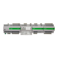
Illustration
Description
8-Way MS/TP address DIP switch (CBX only)
The controller’s BACnet® MAC address can be set either electronically (USB or BACnet®) or manually using the 8-way
DIP switch.
1)
Manual setting for ease of replacement
: Setting the 8-way DIP switch to an address between 1 and 254, and
then cycling the power, will force the controller to update its MAC address to match the DIP settings. To
replace a manually-addressed controller in the field simply copy the DIP switch setting of the controller you are
replacing.
2)
Electronic setting for remote configuration
: Setting the 8-way DIP switch to all zeros will allow the MAC address
to be set electronically either locally by USB or remotely over BACnet®.
It is also possible to use manual setting for initial commissioning, and then cycling the power to force the
controller to update its MAC address to match the DIP settings. To enable subsequent electronic configuration,
set the DIP switch to all zeros. The controller will retain the manually-set address until it is electronically
overwritten.
5-Way FLX bus address DIP switch (FLX only).
This sets the address of the FLX unit on its local FLX bus.
Output Override (-H variants only: CBX-8R8-H, FLX-8R8-H, FLX-4R4-H)
Bottom position
: Off - outputs forced off.
: Auto - outputs are controlled by strategy.
: Manual – for digital outputs, the output is forced on. For analog outputs the knob setting controls the
output value.
Note: Manual position is supervised, i.e. the strategy is aware of the manual value.
Inter-module connection sockets
Off On Slow Blink Fast blink
Power is off Power is on
____
Unit Rebooting
____
Unit is not
running
Strategy Loaded
but no network
connectivity
Strategy Loaded and
device communicating
on network
No Strategy
loaded
FLX bus
comms are ok
No FLX bus comms FLX bus address clash
FLX bus comms
error
During firmware upgrade the Yellow LED will remain on while the strategy/comms section reboots, and then the
LEDs will rotate Red-Green-Yellow while the IO section reboots.
Note: During typical operation, the Red LED should be on, the Green
LED should be blinking, and the Yellow LED should be off.
 Loading...