DS0119 rev 40 ©2018 Cylon All Rights Reserved. Subject to change without notice
WWW.CYLON.COM
WWW.CYLON-AUTOMATRIX.COM
CBX System
TECHNICAL DATASHEET & INSTALLATION GUIDE
INSTALLATION GUIDE
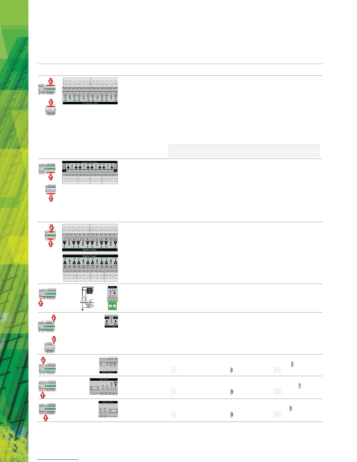
TERMINALS
Location
Illustration
When input is configured as
: open circuit or logic 'off'
• LED
: logic 'on'
When input is configured as
: valid resistance connected (
: 0 Ω is counted as valid)
• LED
: resistor/thermistor not connected
When input is configured as
:
• LED intensity is modulated by the analog signal
When the LED is blinking:
•
indicates error condition
•
indicates the input is in an override state (overridden
by CXpro
HD
).
*Note: The LED intensity illustrates the value measured at the input terminals. The flash
indicates that this value has been overridden.
25 … 38
When a Uniput
TM
channel is configured as an input, the LED signals are identical to Universal Inputs
above. When configured as an output the following apply:
When output is configured as
: open circuit or logic 'off'
• LED
: logic 'on'
When output is configured as
:
• LED intensity is modulated by the analog signal
When the LED is blinking:
•
indicates error condition
•
indicates the output is in an override state
1 … 12,
26 … 37
Digital Inputs (FLX16DI only)
• LED
: open circuit or logic 'off'
• LED
: logic 'on'
When the LED is blinking:
•
indicates error condition
•
indicates the output is in an override state
(overridden by CXpro
HD
).
Auxiliary Power: 18 V DC output on 2 terminals, 60 mA total
BACnet® MS/TP Port (RS-485) screw terminal
MS/TP subnet terminator switch is located beside the port. If the switch is towards the
icon, then
termination is in and if the switch is towards the
icon then termination is out.
UCU Room Display / CBT-STAT Port
The CBT-STAT bus Terminator Switch is located beside the port. If the switch is towards the
icon, then
termination is in and if the switch is towards the
icon then termination is out.
The Modbus Terminator Switch is located beside the port. If the switch is towards the
icon, then
termination is in and if the switch is towards the
icon then termination is out.
 Loading...