DS0119 rev 40 ©2018 Cylon All Rights Reserved. Subject to change without notice
WWW.CYLON.COM
WWW.CYLON-AUTOMATRIX.COM
CBX System
TECHNICAL DATASHEET & INSTALLATION GUIDE
Note: If there are 2 devices on the same FLX bus with the same address –including
0, the address of the CBX - then the bottom (yellow) status LED will blink
slowly to indicate a FLX bus address clash
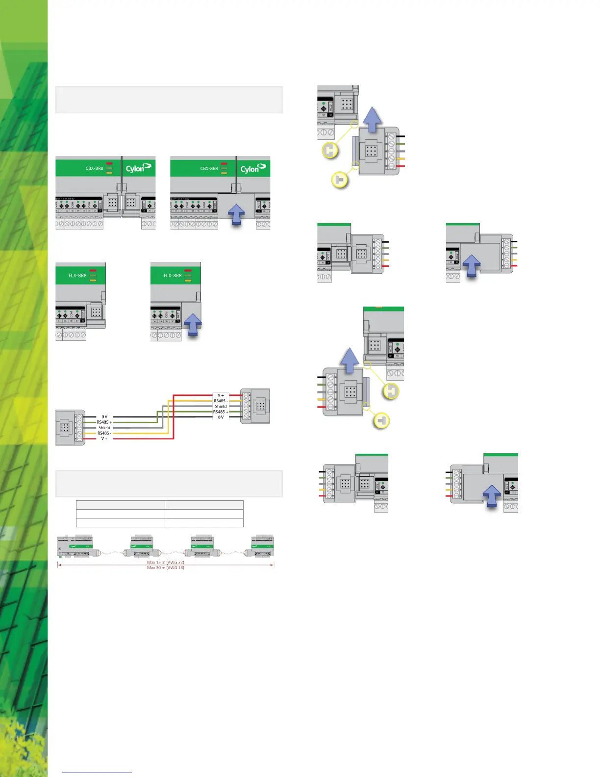
4.2. Join or terminate the FLX bus
Place the devices side-by-side and place the FLX bus connector into
the two adjacent sockets at once.
The end device on a CBX set (either a FLX device or the CBX itself if no FLX devices
are connected) must have a terminator inserted into its interconnector socket.
One terminator is shipped with each CBX-8R8(-H) device.
4.3. (If required) Set up FLX bus extension
If a FLX device cannot be located beside a CBX device or another FLX device then
The FLX bus can be connected by cable using two FLX-RMC Remote Module
Connectors, sold separately.
Connect cables to the two supplied FLX-RMC screw-terminal connectors as shown
above with the appropriate length of cable.
Note: Use Copper or Copper Clad Aluminum conductors only. Multiple wired
connections can be used between FLX modules, but the total FLX bus FLX
bus length must not exceed the following lengths:
Remove the Interconnect (if installed) from the right-hand side of the FLX or CBX
where the RMC is to be installed.
Slide one RMC connector into the T-slot of the CBX or FLX at the point at which
the BUS is to be extended.
Replace the Interconnect
Slide the other RMC connector into the Left-Hand T-slot of the remote FLX.
Insert the second interconnect
 Loading...