USEWITHAPSX‐R
©CyrusAudioLtdJun2014 16 Cyrus6DAC,Cyrus8DACservicemanualIssue1
UsewithaPSX‐R
WhenaPSX‐Rpowersupply isconnectedtoaCyrus8DAC,thepresenceofpowerasthePSX‐R
isswitchedfromstandbyautomaticallydisconnectsthefeedfromtheinternal powersupplyto
the preamplifier regulators (via switch transistors T406/T402). The power from the PSX‐R is
thenfedtothepreamplifierregulatorsviaD451/D454.
NomodificationisnecessarytotheamplifierforusewithaPSX‐R,itmaybeconnectedwithout
anychangestotheamplifier.
TheconnectionsbetweentheamplifierandPSX‐Rfunctionasfollows‐
Pin1(Standby)
This is an output from the amplifier to send a standby control message (logic 1, +5V) to the
PSX‐R,enabling the regulated powersuppliesofthePSX‐R.Notethatthispinwillnot change
stateiftheamplifierdetectsafault(Seepin5).
Pin2(Positivesupply)
InCyrus8DACamplifiers,thispindelivers+18VfromthePSX‐Rtotheamplifier,switchedby
theStandbycontrolsystem.
Pin3(GND)
ThispinisthesystemgroundreturnbetweentheamplifierandPSX‐R.
Pin4(Negativesupply)
In Cyrus 8 DAC amplifiers,thispin delivers‐18V from thePSX‐R to theamplifier,switchedby
theStandbycontrolsystem.
Pin5(PSX‐Rdetect)
Thispinisaninputtothe amplifiertodetectthepresenceofaworkingPSX‐R.Thepinalsosets
the working mode of the PSX‐R. T408 and associated components act on the line to set a
referencevoltagethatswitchesthePSX‐Rtovariablemode,set
for18Vsupply.
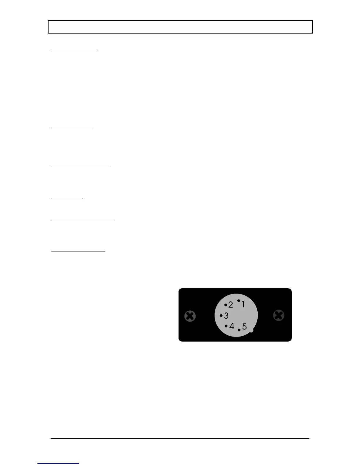
This diagram shows the pin numbers of the
power supply input connector on the
amplifier.Viewisoftheconnectorpinsfrom
therearoftheamplifier