FAULTFINDING/DISASSEMBLY
©CyrusAudioLtdJun2014 9 CDtServiceManualIssue1
Removingtheloadingmechanismwithlaserpickup
Disconnectmainspower.
DisconnecttheflexfoilfromCON405ontheservoPCB.
Removethetwoscrewssecuringthemountingcradletothechassis.
Slide the loader and cradle back in the chassis to disengage the front, then lift the
completeassemblyfromthechassis.
Removingthecradle
OncethePCBhasbeenremoved,thecradlecanbeseparatedfromtheloaderafterremoving
thetwoself‐lockingnuts.
RemovingtheservoPCB
In a static safe environment, disconnect the flex foil from CON401 on the servo PCB. Use a
metal paper clip to short the exposed end of the flex‐foil and protect from static damage.
DisconnectthecableplugsfromCON402,CON403 andCON404. ThePCBsecuringscrewscan
nowberemovedandtheservoPCBliftedclear.
Replacingtheloadingmechanismwithlaserpickup
Replacementisgenerallyareversalofremoval,butnotethefollowingimportantsteps‐
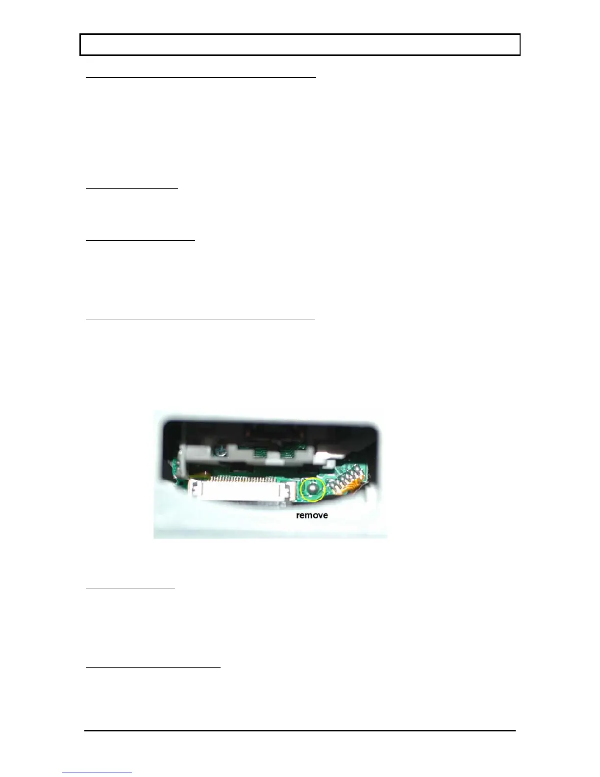
Oncethe servo PCB has been fitted and the flexfoil cablefrom the laser pickupconnectedto
CON401, the solder‐short that protects the pickup from static must be removed. This is
accessiblethroughthewindowontopoftheloaderasshown.
Removalofthesolder‐shortstaticprotection:
Once the solder‐short is removed, the loader can be fitted to the cradle and then to the
chassis.
Digitaloutputfaults
The digital output drive circuits arerelativelystraightforward.If the discis playing, check the
presence of the digital output signal from the DOBM pin of CON405 on the servo PCB. This
signalshouldthenappearon the mainPCBatIC601,thenIC604beforepassing through L402
tothe
digitaloutputs.
RemovingthefrontpanelPCB
Ifa fault isdiagnosedwhichrequires the removal of thefront panel PCB,proceedasfollows.
First, following the instructions above, remove the loading mechanism. Now disconnect the
flexfoil running to the front panel PCB. Finally, the complete front panel assembly including
display PCB may now be pressed forward out of the front of the chassis. Remove the fixing