ADDITIONAL INFORMATION Cyrus Pre
English
18
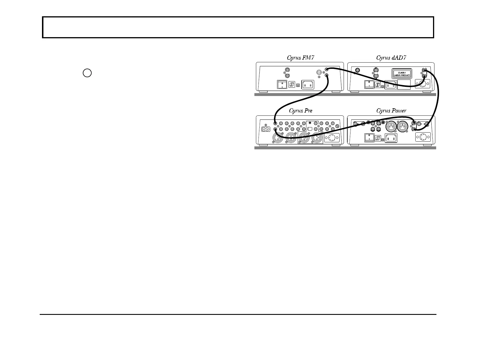
MC-BUS System Connection
•
This is an optional connection via the MC-Bus
sockets
2
(see rear panel drawing on page 4), which
can provide unified power control of a complete
Cyrus system from your Cyrus Pre. The MC-Bus
connections should be wired as a 'loop' using single
RCA phono interconnects. The diagram on the right
shows a typical Cyrus system of Cyrus dAD7, Cyrus
FM7, Cyrus Pre and Cyrus Power with such an MC-
Bus loop connected. Referring to this diagram,
connect the first cable between the MC-Bus output of
the Cyrus Pre and the MC-Bus input of the next
Cyrus component. Continue to wire each product
MC-Bus output to the next input, finally returning to
the Cyrus Pre input to complete the loop.
Operating a system with MC-Bus connected
•
When the above connections have been made it will
now be possible to control the power function of the
entire system from the Cyrus Pre, either from the
front panel or by remote control. Selecting 'CD' from
the Cyrus Pre front panel will then switch on the
Cyrus Pre, the Cyrus Power and the Cyrus dAD7 CD
player. When the Cyrus Pre is set to Standby, all
system components will also switch off.
•
Another important function of the MC-Bus system is
to enable Micro-processor controlled testing and
calibration to be applied during the production phase
of the Cyrus range of products. Using the MC-Bus all
possible tests relating to the correct operation of the
system are performed in a relatively short period of
time. Such rigorous tests are only possible with the
aid of this proprietary communication bus system
which ensures consistency and quality levels hitherto
impossible to achieve in an audio product of this
price range.