13
IDENTIFYING EXTERNAL COMPONENTS
This chapter describes the front panel, rear panel, and LED indicators
of the Switch.
Front Panel
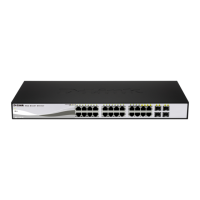
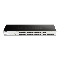
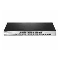
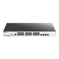
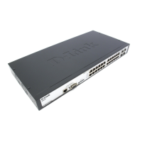
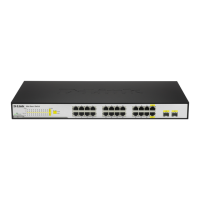
The figure below shows the front panel of the Switch.
Figure 4 – Front panel of the 24-port Web-Smart Switch
LED Indicator:
Comprehensive LED indicators display the status of the switch and
the network (see the Understanding LED Indicators section).
Gigabit Ethernet Ports (Port 1~24):
The Switch includes twenty four Gigabit twisted pair ports, each
supporting auto negotiable 10/100/1000Mbps and auto MDI/MDIX
crossover detection functions. This function provides true “plug and
play” capability. These ports can operate in half-duplex mode for
10/100Mbps and full-duplex mode for 10/100/1000Mbps.
Mini GBIC Ports(Option Port 23~24)
The Switch is equipped with two mini-GBIC ports, supporting an
optional 1000BASE-SX/LX mini-GBIC module.
Note: When a port is set to “Forced Mode”, the Auto MDI/MDIX
will be disabled.
 Loading...