DGS-3130 Series Layer 3 Stackable Managed Switch Hardware Installation Guide
24
Side Panel Components
The side panels of this switch contain heat vents, fans, and rack-mounting screw holes. The heat vents are used to
dissipate internal heat and facilitate internal air circulation. Do not block these openings. Leave at least 4 inches of
space at the sides of the Switch for proper ventilation. Without proper heat dissipation and air circulation, system
components might overheat which could lead to system failure or even severely damaged components.
Figure 2-16 Side panels of the DGS-3130-54TS
DGS-3130-54S Switch
Front Panel Components
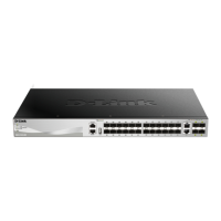
The front panel of DGS-3130-54S features a variety of LED indicators and ports.
Figure 2-17 Front panel view of the DGS-3130-54S
Ports that can be found on the front panel of this switch are listed in the table below.
Port Description
100/1000 Mbps SFP Ports The Switch is equipped with 48 SFP ports. These ports can operate at 100 Mbps
and 1 Gbps wire-speeds.
10 Gigabit RJ45 Ports The Switch is equipped with 2 RJ45 Ethernet ports. These ports can operate at 1
Gbps and 10 Gbps wire-speeds.
10 Gigabit SFP+ Ports
The Switch is equipped with 4 SFP+ ports. These ports can operate at 1 Gbps and
10 Gbps wire-speeds and support a wide collection of SFP+ transceivers.
For a complete list of SFP/SFP+ transceivers that are compatible with this switch, refer to the SFP Ports and SFP+
Ports sections in Appendix A - Technical Specifications.
LED Indicators
Located on the front panel of this switch are LED indicators: Power, Console, RPS, Fan Err, USB, Link/Act indicators
for all the ports, and Stack ID.

 Loading...