DIS-200G Series Layer 2 Gigabit Industrial Smart Managed Switch Hardware Installation Guide
9
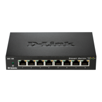
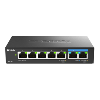
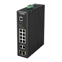
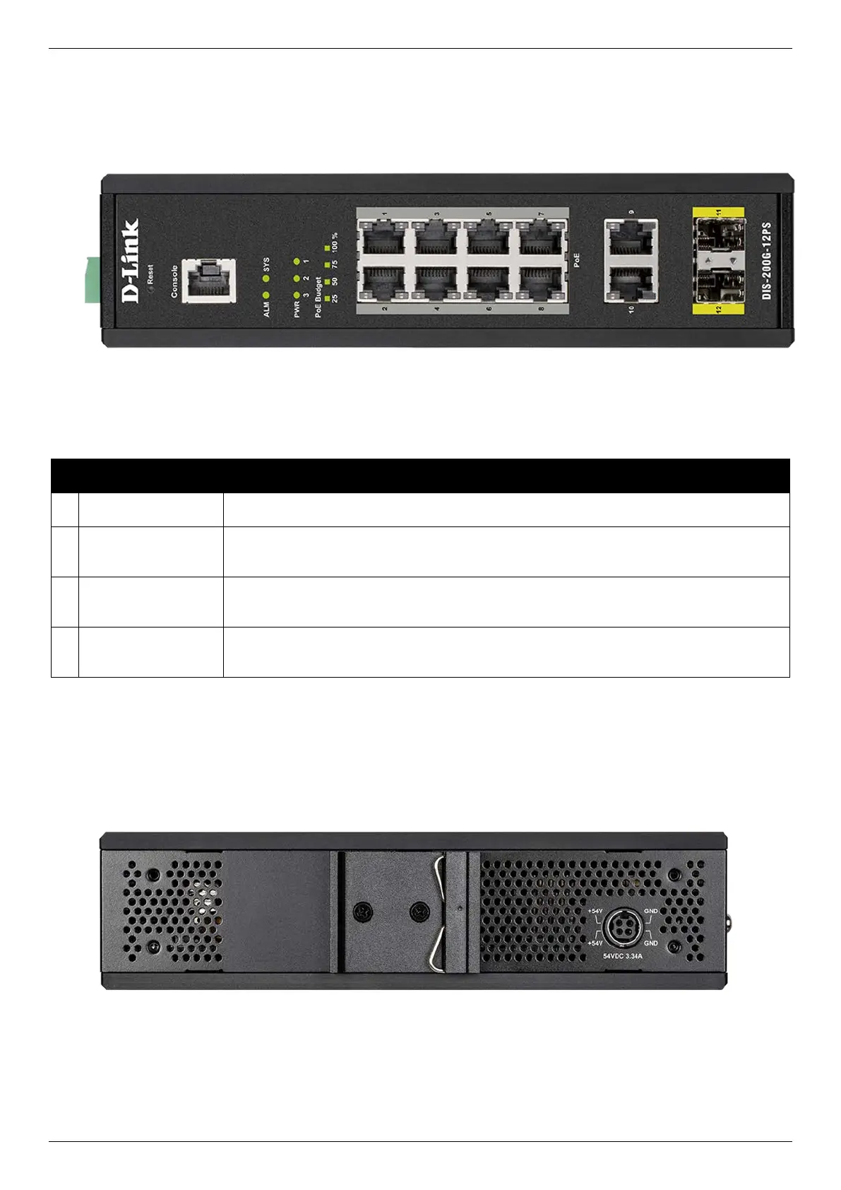
Front Panel Components
Below is an overview of the interface present on all switch models in the DIS-200G series.
Figure 1-1 Front panel view of the DIS-200G Series switches
Ports that can be found on the front panel of this switch are listed in the table below.
LED Description
1 Reset
This the reset button which is used to perform a factory reset.
2 Console
This is a console port which is used to connect to the DIS-200G switch using a RJ-45 to
serial cable.
3 Ports 1 - 10
These are 10/100/1000 Mbps ports that can be used to connect to any device using a
standard Category 5/5e RJ-45 Ethernet cable.
4 Ports 11 - 12
These are 1 Gbps SFP ports that can be used to connect to other switches using
compatible SFP adapters and fiber cable.
For a complete list of SFP transceivers that are compatible with this switch, refer to the Supported Transceivers
section in Appendix A - Technical Specifications.
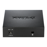
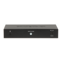
Rear Panel Components
Figure 1-2 Rear panel view of the DIS-200G Series switches
Ports that can be found on the rear panel of this switch are listed in the table below.
 Loading...