DSS-100E-9P
2
ENGLISH
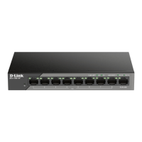
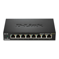
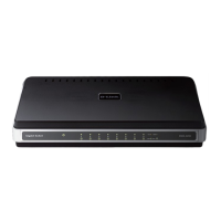
Front Panel Connectors
Figure 2: Front panel connectors
# Interface Description
1 Ports 1 - 8
10/100 Mbps PoE-capable ports,
used for connecting Ethernet
devices and PoE-powered devices.
2 Ports 9
10/100/1000 Mbps Ethernet
port for uplink connections to
NVR, storage or core switch.
Table 2: Front connector description
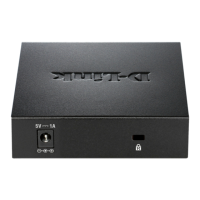
Rear Panel Connectors
Figure 3: Rear panel connectors
# Connector Description
1 DC Power Input Input jack for the power adapter.
2 SWITCH GND
Screw used to secure a grounding
wire to connect the switch to ground.
Table 3: Rear connector description
Extended Mode
The DSS-100E-9P can automatically detect the long
reach requirement and activate Extended without
manual conguration.
P.S. The actual transmission distance will be aected
by cable quality or connected IP Camera design. The
device can support up to 250m application with
Cat5e above ethernet cable, but the transmission
may drop to 10Mbps speed or below.
Hardware Installation
Installation Precautions
For safe switch installation and operation, it is
recommended to:
Before You Begin
This Quick Installation Guide gives you step-by-step
instructions for setting up your DSS-100E-9P 9-port
10/100 PoE Surveillance Switch. The model you have
purchased may appear slightly dierent from the
one shown in the illustrations.
Package Contents
This DSS-100E-9P package should include the
following items:
• 1 x DSS-100E-9P
• 1 x Power cord
• 1 x Power adaptor
• 1 x Quick Installation Guide
If any of the above items are damaged or missing,
please contact your local D-Link reseller.
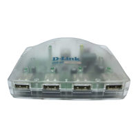
Hardware Overview
LED Indicators
Figure 1: Front panel LEDs
# LED Status Description
1 Power
Solid
green
The switch is powered on.
O The switch is turned o.
2
Link/
ACT/
Speed
(Left
Led)
Solid
green
There is an active link negotiated
on this port.
Blinking
green
There is trac on the port.
O There is no active link on this port.
3
PoE
(Right
Led)
Solid
green
The port is providing power to the
connected PoE-powered device.
Blinking
green
Indicates a PoE-powered device
is connected to this PoE port,
but the switch has insufficient
remaining power budget to
power the device.
O There is no PoE-powered device
connected to this port.
Table 1: LED overview
1 2
1
1 2
3
2