xStack
®
DGS-3120 Series Layer 2 Managed Stackable Gigabit Switch Hardware Installation Guide
15
Connect to a Redundant Power Supply
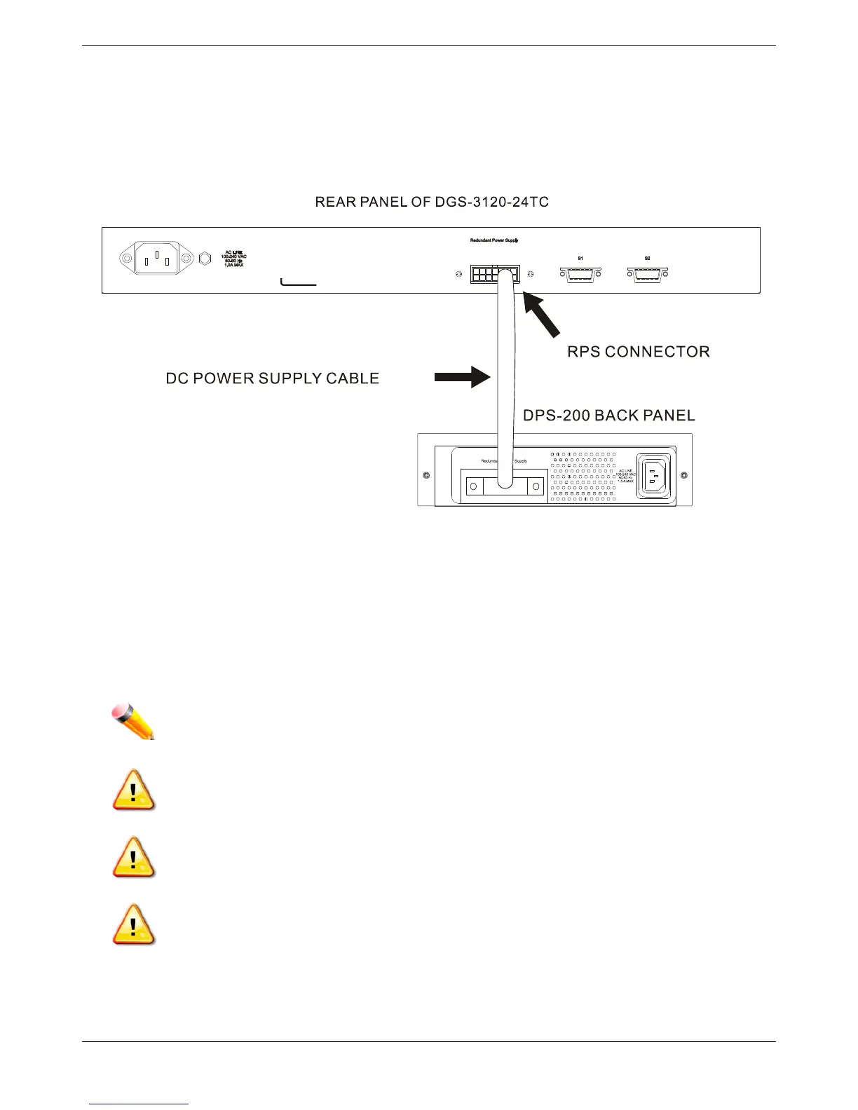
The DPS-200 or DPS-500 is connected to the Master Switch using a 14-pin DC power cable. A standard, three-
pronged AC power cable connects the redundant power supply to the main power source.
Figure 2- 6. Connecting the DGS-3120-24TC to the DPS-200
1. Insert one end of the 14-pin DC power cable into the receptacle on the switch and the other end into the
redundant power supply.
2. Using a standard AC power cable, connect the redundant power supply to the main AC power source. A
green LED on the front of the DPS-200 or DPS-500 will glow to indicate a successful connection.
3. Re-connect the Switch to the AC power source. The LED indicator will show that a redundant power supply is
now in operation.
4. No change in switch configuration is necessary for this installation.
NOTE: See the RPS Quick Installation Guide for more information.
CAUTION: DO NOT use the DGS-3120-24TC/24SC switch with any redundant power system
other than the DPS-200.
CAUTION: DO NOT use the DGS-3120-48TC switch with any redundant power system other than
the DPS-500 and the DPS-500DC.
CAUTION: DO NOT use the DGS-3120-24PC and the DGS-3120-48PC switch with any redundant
power system other than the DPS-700.