xStack
®
DGS-3120 Series Layer 2 Managed Stackable Gigabit Switch Hardware Installation Guide
16
External Redundant Power System
The DPS-200 and DPS-500 are redundant power supply units designed to conform to the voltage requirements of the
switches being supported. The DPS-200 and DPS-500 can both be installed into a DPS-900, or DPS-800 rack mount
unit.
The DPS-200 can only be used with the DGS-3120-24TC and the DGS-3120-24SC.
The DPS-500 can only be used with the DGS-3120-48TC.
The DPS-700 can only be used with the DGS-3120-24PC and the DGS-312048PC.
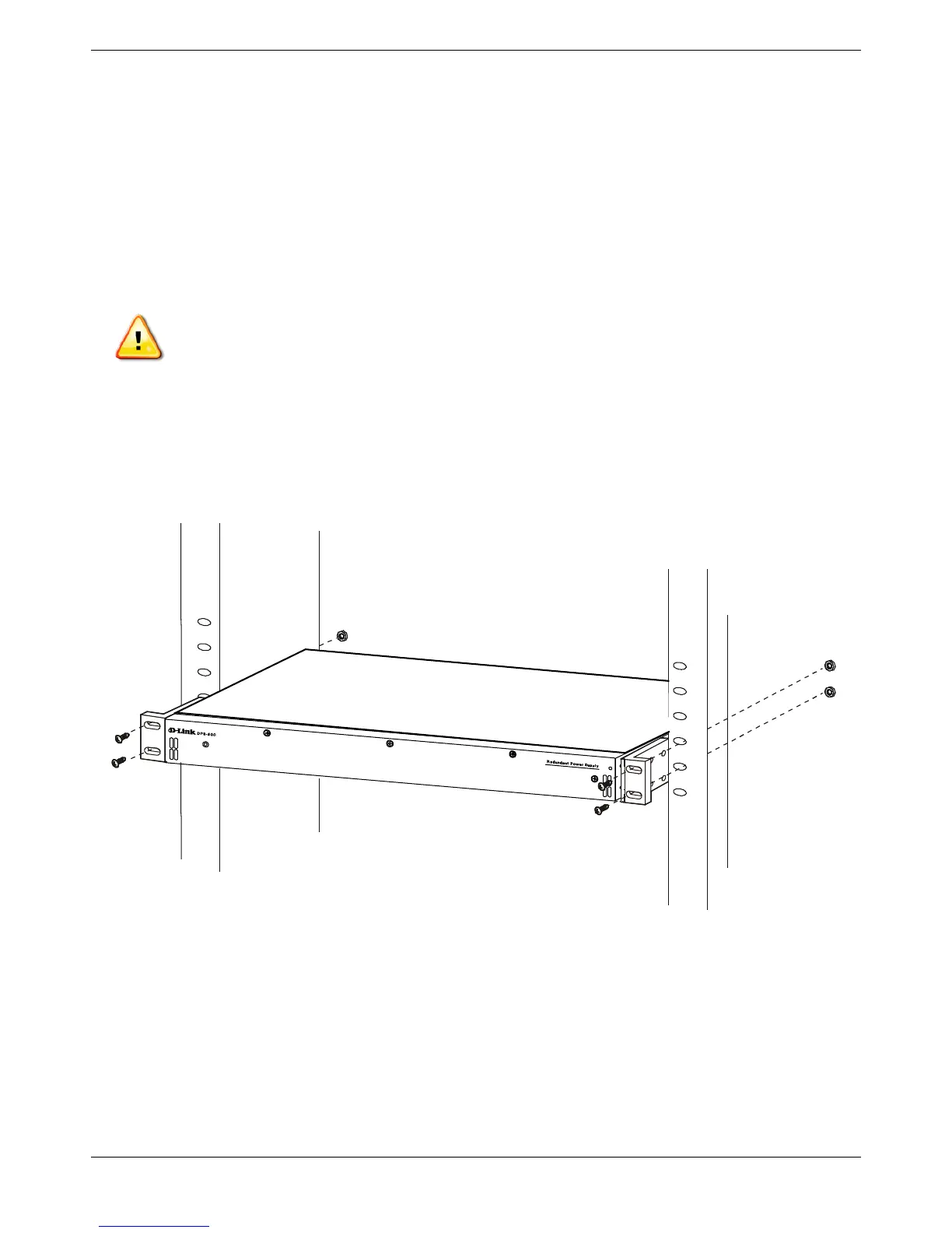
DPS-700
The DPS-700 is connected to the Master Switch using a 22-pin DC power cable. A standard, three-pronged AC power
cable connects the redundant power supply to the main power source.
Figure 2- 7. Front view of the DPS-700
1. Insert one end of the 22-pin DC power cable into the receptacle on the Switch and the other end into the
Redundant Power Supply unit.
2. Using a standard AC power cable, connect the redundant power supply to the main AC power source. A
green LED on the front of the DPS-700 will glow to indicate a successful connection.
3. Re-connect the Switch to the AC power source. The LED indicator will show that a redundant power supply is
now in operation.
4. No configuration in the Switch’s firmware is needed for this installation.
CAUTION: DO NOT connect the RPS to AC power before the DC power cable is connected. This
might damage the internal power supply.