ENGLISH
44
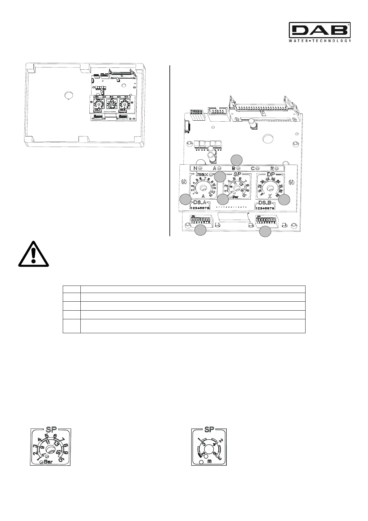
10. PANEL INTERNAL REGULATING BOARD
Before starting regulation, switch off the mains power by means of the
insulating switch QS1.
To access the internal panel, slacken the screws, turn the cover of the electric panel downwards and operate the
commands.
Ref. Function
1 Warning lights for activating the digital inputs (N-A-B-C-R).
2
Trimmer for regulating the system (Imax – SP – DP).
3
Dip-switch for selecting functions (DS_A – DS_B).
4
Led indicating current overload set at the motor data plate values.
For a correct settin
the Led must be off.
10.1 Trimmer for regulating the system (Imax – SP – DP)
T1 – Trimmer (Imax)
Trimmer for setting the maximum current for the two electropumps P1 and P2 (0.25A –13A).
Set the Trimmer at the motor data plate value (the yellow led must be off).
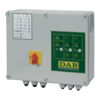
T2 – Trimmer (SP – system Set Point) / Trimmer 3 (DP – Pressure level differential)
Trimmer for setting the pressures or level of the system.
The trimmer SP (set by DS_B5) presents a double regulating scale in bar: from 1 to 10 bar or from 7 to 15 bar
corresponding to the led lit, if a pressure sensor is used in the booster sets. This scale may also be expressed in
metres (as an optional version, using the plate supplied): from 1 to 3 metres or from 2 to 5 metres always
corresponding to the led lit, if an analog level sensor is used in the filling and draining sets.
DP regulation is expressed as a percentage of the value set in SP.
1
2
3
3
2
2
4
Standard regulation in bar
Optional regulation in metres
(plate supplied)