ENGLISH
49
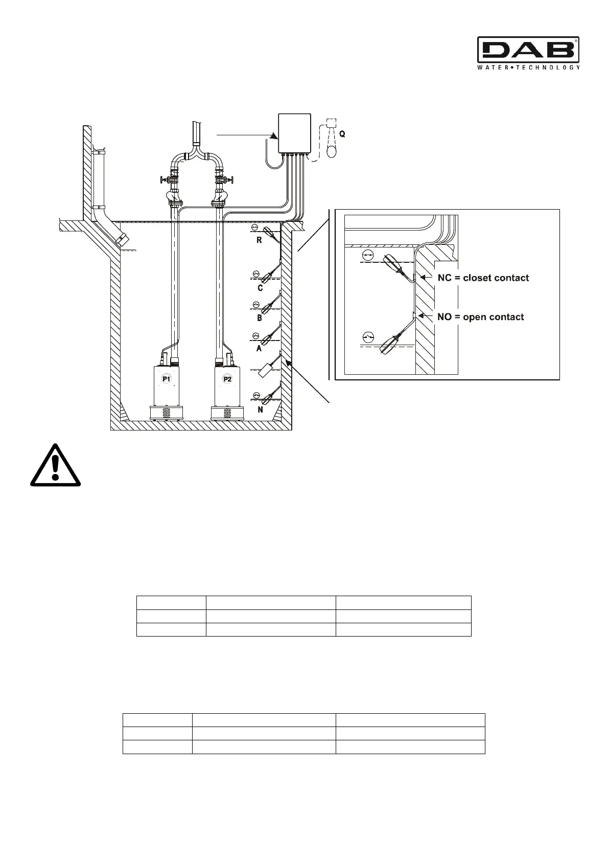
13. DRAINING FUNCTION
In draining function (drainage) the floats, if present, are positioned in this order:
Do not touch and clean the sensor membrane with your hands, screwdrivers, brushes, etc.!
Do not clean the membrane with compressed air!
The transmitter must be steeped in water and cleaned only with soap and water or with
alcohol!
Do not drop the transmitter and do not tap it on the table to get the residue out!
Do not blow into the cable compensation hose! Do not pull the cable!
13.1 Operation with 2 floats
In operation with 2 floats, Pump P1 starts with the closed contact of the float B, while Pump P2 starts with the
closed contact of the float C.
Both pumps stop with the open contact of the float B.
The following table sums up the behaviour described:
Sequence Pump P1
Pump P2
START
Float B = NC
Float C = NC
STOP
Float B+C = NO
Float B+C = NO
13.2 Operation with 3 floats
In operation with 3 floats, Pump P1 starts with the closed contact of the float B, while Pump P2 starts with the
closed contact of the float C.
The pumps stop with the open contact of the float A which controls the minimum level for both.
The following table sums up the behaviour described:
Sequence Pump P1
Pump P2
START
Float B = NC
Float C = NC
STOP
Float A+B+C = NO
Float A+B+C = NO
N.B. Instead of the floats, electric probes may be connected.
ONLY WITH CLEAN CLEAR WATER!
analog level sensor
ELECTRIC
PANEL