8
I
GB
SX1000 SX1500 SX2000
CH 1 / BRIDGE
BRIDGE
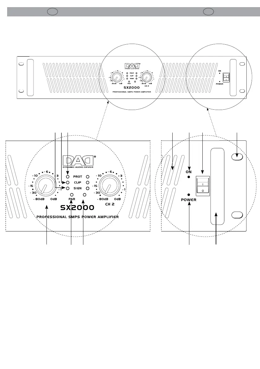
Elementi di comando e collegamenti Operating elements and connections
1. MANIGLIE.
2. FORI DI FISSAGGIO per il montaggio rack.
3. INTERRUTTORE ON/POWER.
4. INDICATORE ON DI ACCENSIONE: quando acceso,
l’amplicatore è alimentato correttamente.
5. INDICATORE POWER: si accende quando si
connette l’amplicatore all’alimentazione.
Quando si pone l’interruttore di accensione su
on invece si spegne e si accende l’indicatore di
accensione.
6. PRESE DI VENTILAZIONE: aperture per entrata
usso d’aria da non ostruire.
7. CONTROLLI DI LIVELLO ROTATIVI A SCATTI:
potenziometri per l’attenuazione del guadagno
d’ingresso.
1. HANDLES.
2. MOUNTING HOLES for xing the rack.
3. POWER SWITCH ON/POWER.
4. ON INDICATOR: when this indicator is on, the
amplier main power supply is working.
5. POWER INDICATOR: the standby LED lights up
when the amplier is connected to the power
supply. When the power switch is set to ON
position, the standby LED turns o and the
power ON LED lights up.
6. VENTILATION OPENINGS: the openings let the
air ow in. Do not obstruct them.
7. ROTARY DETENTED LEVEL CONTROL: Input
gain attenuator potentiometers. Attenuate
PANNELLO FRONTALE FRONT PANEL
CH 1 / BRIDGE
BRIDGE
8 9
7 11 12
10
6 24
5
1
3