Do you have a question about the Daewoo ERF-384 and is the answer not in the manual?
Detailed specifications for various refrigerator models, including dimensions and technical data.
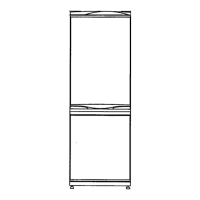
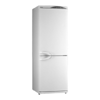
Visual representation of the external dimensions of the ERF-334M model.
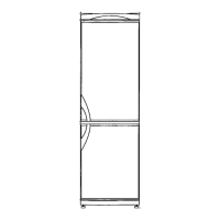
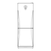
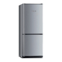
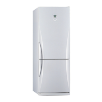
External views and dimensions for several refrigerator models.
Electrical wiring schematic for the ERF-334M refrigerator.
Wiring diagram for the ERF-367A, 387A, 397A, and 417A models.
Wiring diagrams for ERF-364A, 384A, 394A, and 414A models.
Wiring diagrams for ERF-364M, 384M, 394M, and 414M models.
Step-by-step guide for disassembling the refrigerator's control panel.
Instructions for removing the multi-duct cover on M type models.
Procedure for removing and replacing the magnetic seal (gasket).
Steps to disassemble components within the freezer compartment.
Detailed steps for removing and replacing the door switch on the ERF-334M.
Exploded view illustrating the assembly of the ERF-334M refrigerator.
Exploded view showing the parts of the ERF-384M refrigerator.
Exploded view of ERF-364M, ERF-394M, and ERF-414M models.
Exploded view for the ERF-384A refrigerator model.
Exploded view of ERF-364A, ERF-394A, and ERF-414A models.
Exploded view illustrating the assembly of the ERF-387A refrigerator.
Exploded view for ERF-367A, ERF-397A, and ERF-417A models.
Comprehensive list of parts for the ERF-334M model with codes and descriptions.
Parts list for the ERF-384M refrigerator model, including part codes.
Parts list for ERF-364M, ERF-394M, and ERF-414M models.
List of parts for the ERF-384A model, with part numbers and descriptions.
Parts list for ERF-364A, ERF-394A, and ERF-414A models.
Detailed parts list for the ERF-387A refrigerator.
List of parts for ERF-367A, ERF-397A, and ERF-417A models.
Explains the display indicators and error codes for the PCB.
Details on adjusting settings using buttons like CONTROL, FUZZY, and TEMP.
How to adjust and control temperature settings for different modes.
Functionality for the Vacation mode, including LED indicators.
Details on the Turbo mode and its operation.
Conditions and timing for initiating the defrost cycle.
Explains general and forced defrost modes and their processes.
Conditions under which the initial defrost mode starts.
Rules to protect the compressor from frequent starts and stops.
Explains error codes, displays, and control responses for various sensor issues.
Procedure for testing short circuits and the system's response.
How to reduce operational time for testing purposes.
Details on the artificial intelligence function and its control.
Information about the Turbo option for over-cooling protection.
How the system manages low room temperatures and hysteresis.
How to adjust the R-sensor off point using input voltage.
Schematic diagram of the main PCB for specific refrigerator models.
Schematic diagram of the main PCB for ERF-367A, 387A, 397A, 417A models.
| Model | ERF-384 |
|---|---|
| Brand | Daewoo |
| Category | Refrigerator |
| Total Capacity | 384 liters |
| Number of Doors | 2 |
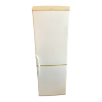
| Color | Silver |
| Shelves Material | Glass |