2 Device Structure
2.1 Rear Panel
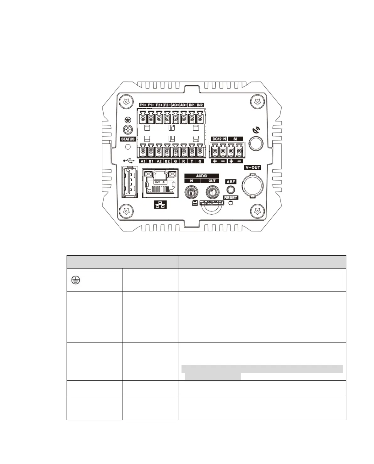
Figure 2- 1
This interface must be grounded, to improve device
reliability, otherwise the device may lose lighting
protection.
It is to indicate camera working status:
The blue light flashes when recording.
The red light flashes when system is upgrading.
The red light flashes in safety mode.
F1+, F1-, F2+,
F2-, AO1, AO2
Switch, may set output flashlight signal and strobe light
signal.
Warning:
Page config must match actual light, otherwise the light
could be damaged.
Provide 4 IO trigger snapshot interfaces or 4 alarm
input interfaces
RS485_A1 interface,this device is used to control NO
light, and others may expand to customize signal
detector, vehicle detector and etc.
 Loading...