EasyManuals Logo

Daikin 4MXS36NMVJU Service Manual

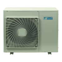
Daikin 4MXS36NMVJU
257 pages
To Next Page IconTo Next Page
To Previous Page IconTo Previous Page
Page #45 background imageLoading...
Page #45 background image
SiUS121630EA Wireless Remote Controller Kit
Printed Circuit Board Connector Wiring Diagram 33
3. Wireless Remote Controller Kit
3.1 BRC082A41W, BRC082A42W(S)
Transmitter
Board (A2P)
Receiver (A3P)
LED5 and LED6 do not function.
1) X1A Connector for receiver (A3P)
2) X2A Connector for control PCB (A1P)
3) SS1 MAIN/SUB setting switch
Refer to page 224 for details.
4) SS2 Address setting switch
Refer to page 224 for details.
3P156326-3
X2A
SS2
SS1
X1A
1) X1A Connector for transmitter board (A2P)
2) BS1 Emergency operation switch
3) LED1 (H1P) LED for operation (red)
4) LED2 (H2P) LED for timer (green)
5) LED3 (H3P) LED for filter cleaning sign (red)
6) LED4 (H4P) LED for defrost operation (orange)
3P174795-1
LED 4
X1A BS1
LED 3
LED 2
LED 1

Table of Contents

Other manuals for Daikin 4MXS36NMVJU

Questions and Answers:

Question and Answer IconNeed help?

Do you have a question about the Daikin 4MXS36NMVJU and is the answer not in the manual?

Daikin 4MXS36NMVJU Specifications

General IconGeneral
Model4MXS36NMVJU
CategoryAir Conditioner
Heating Seasonal Performance Factor (HSPF)4.0
Number of Connectable Indoor Units4
Seasonal Energy Efficiency Ratio (SEER)6.0
RefrigerantR32
Indoor Units CompatibilityCompatible with various indoor units
Indoor Unit Dimensions (HxWxD)Varies by model
Indoor Unit WeightVaries depending on the connected indoor unit model
Operating Temperature (Cooling)-10 to 46 °C
Operating Temperature (Heating)-15 to 24 °C
TypeMulti-Split System

Related product manuals