17 | Technical data
Installer reference guide
235
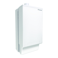
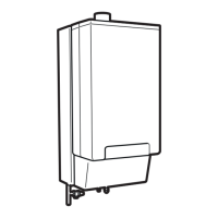
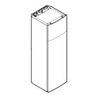
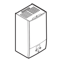
EVLQ05+08CA + EHYHBH05A + EHYHBH/X08A + EHYKOMB33AA
Daikin Altherma hybrid heat pump
4P355634-1G – 2022.09
17.2 Piping diagram: Indoor unit
A B
1
2
3
3
4
5
6
7
8
9
10
20
11
12
13
14
15
16
17
18
19
3D082238-1B
A Water side
B Refrigerant side
1 Space heating/cooling water IN
2 Space heating/cooling water OUT
3 Shut‑off valve with drain/fill valve
4 Expansion vessel
5 Filter
6 Pump
7 Plate heat exchanger
8 Air purge
9 Flow sensor
10 3‑way valve
11 Safety valve
12 Gas boiler
13 Domestic hot water: hot water OUT
14 Gas pipe
15 Domestic hot water: hot water IN
16 R1T – Plate heat exchanger outlet water thermistor
17 R2T – Outlet water thermistor
18 R3T – Heat exchanger liquid pipe thermistor
19 R4T – Inlet water thermistor
20 Screw connection (only for EHYHBH05+EHYHBH08)
Screw connection
Quick coupling
Brazed connection
Flare connection

 Loading...
