B
bryan98Aug 15, 2025
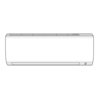
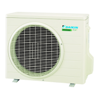
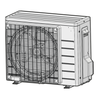
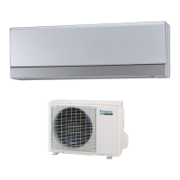
Why is my Daikin Air Conditioner cooling (heating) effect poor?
- WwhitejasonAug 15, 2025
If the cooling or heating effect of your Daikin Air Conditioner is poor, check the following: Ensure the air filters are clean. Make sure nothing is blocking the air inlet or outlet of either the indoor or outdoor units. Verify the temperature setting is correct. Confirm that windows and doors are closed. Check the air flow rate and air direction. Finally, see if the unit is set to INTELLIGENT EYE mode.