20
SERVICING
The maximum and minimum allowable external static pres-
sures are found in the specication section. These tables
also show the amount of air being delivered at a given static
by a given motor speed or pulley adjustment.
The furnace motor cannot deliver proper air quantities (CFM)
against statics other than those listed.
Too great of an external static pressure will result in insu-
cient air that can cause excessive temperature rise, resulting
in limit tripping, etc. Whereas not enough static may result in
motor overloading.
To determine proper air movement, proceed as follows:
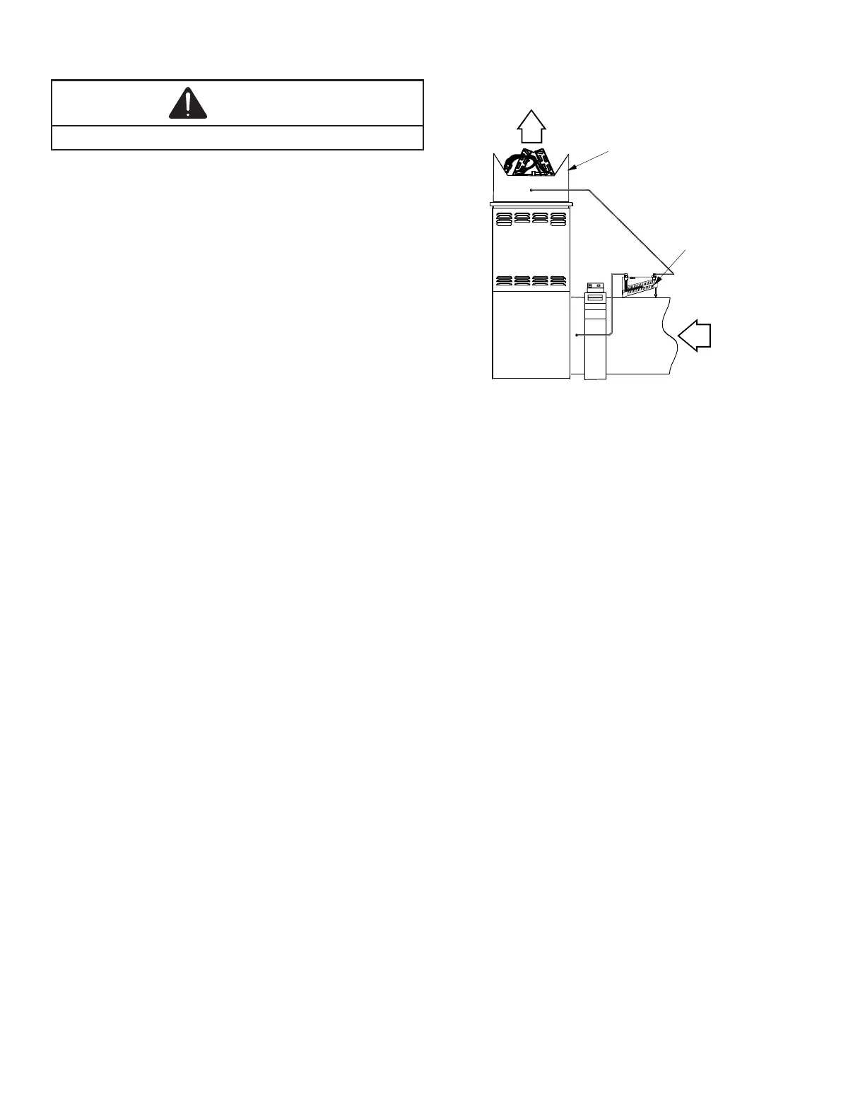
1. With clean lters in the furnace, use a draft gauge
(inclined manometer) to measure the static pressure
of the return duct at the inlet of the furnace. (Negative
Pressure)
2. Measure the static pressure of the supply duct. (Pos-
itive Pressure)
3. Add the two (2) readings together for total external
static pressure.
4. Consult proper tables for the quantity of air.
If the total external static pressure exceeds the minimum or
maximum allowable statics, check for closed dampers, reg-
isters, undersized and/or oversized poorly laid out duct work.
A mana
Electronic Air Cleaner
Ca ution
High V oltage
To avoi d per sonal i n jury, wai t 15
secon ds afte r de -ene rgiz ing u nit
before touch ing unit interior.
CUTAWAY OF DUCTWORK
TO EXPOSE COIL
SUPPLY
AIR
INCLINED
MANOMETER
RETURN
AIR
The more air (CFM) being delivered through a given fur-
nace, the less the rise will be; so the less air (CFM) being
delivered, the greater the rise. The temperature rise should
be adjusted in accordance to a given furnace specications
and its external static pressure. An incorrect temperature
rise may result in condensing in or overheating of the heat
exchanger. An airow and temperature rise table is provided
in the blower performance specication section. Determine
and adjust temperature rise as follows:
1. Operate furnace with burners ring for approximately
ten minutes. Check BTU input to furnace - do not ex-
ceed input rating stamped on rating plate. Ensure all
registers are open and all duct dampers are in their
nal (fully or partially open) position.
2. Place thermometers in the return and supply ducts as
close to the furnace as possible. Thermometers must
not be inuenced by radiant heat by being able to
“see” the heat exchanger.