23
SERVICING
-
-
1. Remove burner compartment door to gain access to
the induced draft blower motor.
2. Disconnect the motor wire leads from its connection
point at the induced draft motor.
3. Using a ohmmeter, test for continuity between each
of the motor leads.
4. Touch one probe of the ohmmeter to the motor frame
(ground) and the other probe in turn to each lead. If
the windings do not test continuous or a reading is
obtained to ground, replace the motor.
5. If the windings have a continuity reading, reconnect
wires. Turn power on to the furnace and turn the
thermostat on in the heating mode. Check voltage for
115V at the induced draft motor terminals during the
trial for ignition. If you have 115V and the motor does
not run, replace the induced draft motor.
6. After completing check and/or replacement of in-
duced draft motor, reinstall burner compartment door.
7. Turn on electrical power and verify proper unit
operation.
A combination redundant operator type gas valve which pro-
vides all manual and automatic control functions required for
gas red heating equipment is used.
The valve provides control of main burner gas ow, pressure
regulation, and 100 percent safety shut-o.
Single stage gas valves should be tested on the furnace with
24 VAC connected to the gas valve and manometers read-
ing supply line and manifold pressures.
The control is designed to open should a ame roll out oc-
cur. An over ring condition or ame impingement on the
heat shield may also cause the control to open. If the rollout
control opens, the air circulation blower will run continuously.
1. Remove the burner compartment door to gain access
to the rollout switch(es) mounted to burner bracket.
The servicer should reset the ignition control by opening
and closing the thermostat circuit. Then look for the ignitor
glowing which indicates there is power to the ignition control.
Measure the voltage between each side of the rollout control
and ground while the ignition control tries to power the gas
valve.
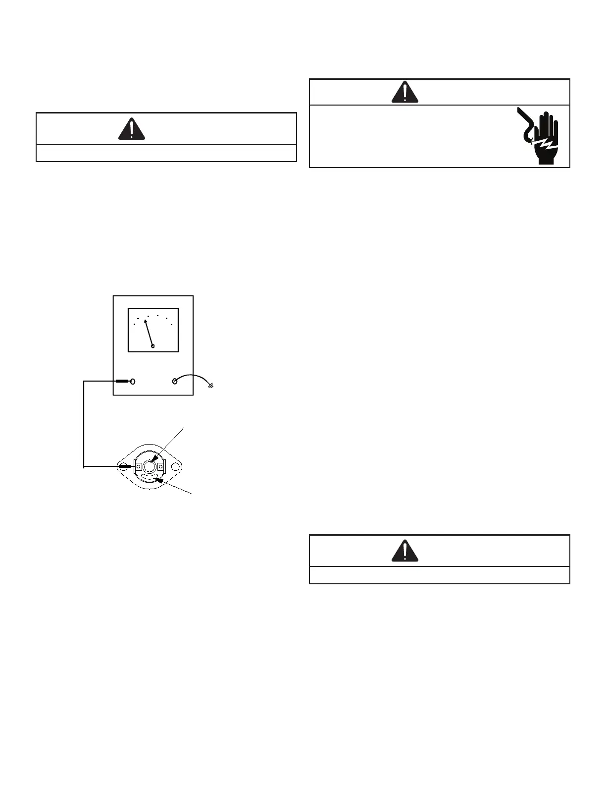
2. Measure the voltage between each side of the rollout
control and ground during the ignition attempt. Refer
to the following gure.
VOLT / OHM
METER
GND
RED
RESET
BUTTON
COLOR
IDENTIFYING
TAB
a. If no voltage is measured on either side of control
it indicates ignition control or wiring to control
problem.
b. If voltage is measured on one side of the control
and not the other it indicates the control is open.
c. If voltage is measured on both sides of the con-
trol the wiring to gas valve or valve is at fault.
3. After check and/or replacement of rollout switch,
reinstall burner compartment door and verify proper
unit operation.