9
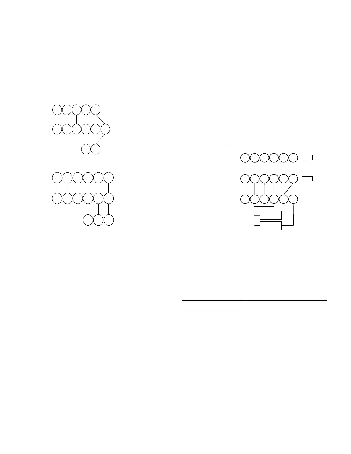
Low voltage connections can be made through either the
right or left side panel. Thermostat wiring entrance holes
are located in the blower compartment. The following gure
shows connections for a “heat/cool system”.
This furnace is equipped with a 40 VA transformer to facili-
tate use with most cooling equipment. Consult the wiring di-
agram, located on the blower compartment door, for further
details of 115 Volt and 24 Volt wiring.
Y
C
Y
C
G
R
W
Y2
Y/Y1
C
G
R
W
ROOM THERMOSTAT
INTEGRATED FURNACE
CONTROL MODULE
REMOTE COOLING UNIT
(SINGLE STAGE)
Y1
C
Y1C
G
R
W
Y2
Y/Y1
C
G
R
W
ROOM THERMOSTAT
INTEGRATED FURNACE
CONTROL MODULE
REMOTE COOLING UNIT
(TWO STAGE)
Y2
Y2
This furnace can be used in conjunction with a heat pump
in a fossil fuel application. A fossil fuel application refers to
a combined gas furnace and heat pump installation which
uses an outdoor temperature sensor to determine the most
cost ecient means of heating (heat pump or gas furnace).
A heat pump thermostat is required to properly use a sin-
gle-stage furnace in conjunction with a heat pump. Refer to
the fossil fuel kit installation instructions for additional ther-
mostat requirements.
Strictly follow the wiring guidelines in the fossil fuel kit in-
stallation instructions. All furnace connections must be made
to the furnace two-stage integrated control module and the
“FURNACE” terminal strip on the fossil fuel control board.
Two furnaces of the same model may be twinned. The in-
tegrated control board has a 3/16” terminal labeled “TWIN”
located beside the low voltage thermostat connection strip.
Twinning allows simultaneous operation of two furnaces and
forces the indoor blower motors of each furnace to oper-
ate synchronously into a common duct system. Using the
twinning function will require only eld installed wiring with
no external kits or parts. The staging and speed tap options
must be set the same on both furnaces.
Each furnace must be connected to it’s own 115 VAC
power supply. The L1 connection to each furnace must be in
phase (connected to circuit breakers on the same 115 VAC
service panel phase leg). To verify that the furnaces are in
phase, check from L1 to L1 on each furnace with a voltme-
ter. If the furnaces are in phase, the voltage between both
furnaces will be ZERO.
ROOM THERMOSTAT
Y2
Y/Y1
C
G
R
W
Y2
Y/Y1
C
G
R
W
Y2
Y/Y1
C
G
R
W
TWIN
TWIN
COND UNIT
CONTACTOR
COND UNIT
CONTACTOR
FURNACE 1
FURNACE 2
-
The furnace integrated control module is equipped with line
voltage accessory terminals for controlling power to an op-
tional eld-supplied humidier and/or electronic air cleaner.
The accessory load specications are noted in the chart:
1.0 Amp maximum at 120 VAC
1.0 Amp maximum at 120 VAC
Turn OFF power to the furnace before installing any acces-
sories. Follow the humidier or air cleaner manufacturers’ in-
structions for locating, mounting, grounding, and controlling
these accessories. Accessory wiring connections are to be
made through the 1/4” quick connect terminals provided on
the furnace integrated control module. The humidier and
electronic air cleaner hot terminals are identied as HUM H
and EAC H. The humidier and electronic air cleaner neutral
terminals are identied as NEUTRAL. All eld wiring must
conform to applicable codes. Connections should be made
as shown.