11
SYSTEM OPERATION
This section gives a basic description of cooling unit opera-
tion, its various components and their basic operation. En-
sure your system is properly sized for heat gain and loss
according to methods of the Air Conditioning Contractors
Association (ACCA) or equivalent.
CONDENSING UNIT
The condenser air is pulled through the condenser coil by
a direct drive propeller fan. This condenser air is then dis-
charged out of the top of the cabinet. These units are de-
signed for free air discharge, so no additional resistance,
like duct work, shall be attached.
The suction and liquid line connections on present models
copper. Front seating or ball valves are factory installed to
normal installation is factory installed in the condensing unit.
DX20VC models are available in 2 through 5 ton sizes and
use R-410A refrigerant. They are designed for 208/230 volt
single phase applications.
DX20VC 2-4 ton R-410A model units use a Daikin rotary
compressor, while the 5 ton has a Daikin Scroll compressor.
refrigerant. These models are Daikin One+ ™ and Comfort-
NetTM ready.
There are a number of design characteristics which are dif-
ferent from the traditional reciprocating and/or scroll com-
pressors.
DX20VC models use "FVC" which is NOT compatible with
mineral oil based lubricants like 3GS. "FVC" oil (required by
the manufacturer) must be used if additional oil is required.
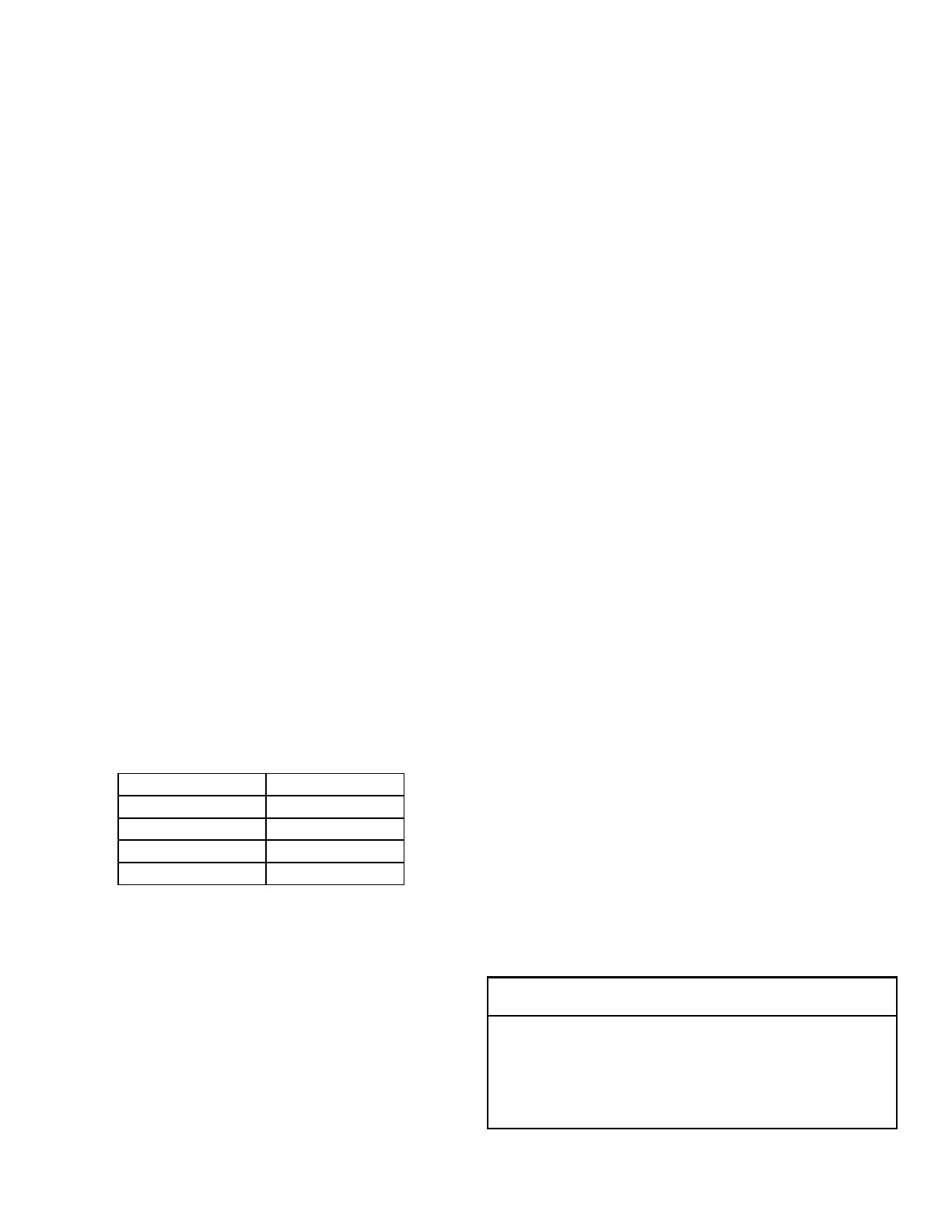
Model Name Compressor Oil
DX20VC0241** FVC50K
DX20VC0361** FVC50K
DX20VC0481** FVC50K
DX20VC0601** FVC68D
COOLING
The refrigerant used in the system is R-410A. It is a clear,
colorless, non-toxic and non-irritating liquid. R-410A is a
50:50 blend of R-32 and R-125. The boiling point at atmo-
spheric pressure is -62.9°F.
A few of the important principles that make the refrigeration
cooler body. Under lower pressure, a refrigerant will absorb
heat and vaporize at a low temperature. The vapors may be
-
ture to be used again.
The indoor evaporator coil functions to cool and dehumidify
the air conditioned spaces through the evaporative process
taking place within the coil tubes.
NOTE: The pressures and temperatures shown in the re-
frigerant cycle illustrations on the following pages are for
demonstration purposes only. Actual temperatures and
pressures are to be obtained from the "Expanded Perfor-
mance Chart".
Liquid refrigerant at condensing pressure and temperatures
leaves the outdoor condensing coil through the drier and is
metered into the indoor coil through the metering device. As
the cool, low pressure, saturated refrigerant enters the tubes
of the indoor coil, a portion of the liquid immediately vaporiz-
es. It continues to soak up heat and vaporizes as it proceeds
through the coil, cooling the indoor coil down to about 48°F.
tubes of the indoor evaporator coil by the warm system air.
This warming process causes the refrigerant to boil. The
As the vapor passes through the last tubes of the coil, it
becomes superheated. That is, it absorbs more heat than is
necessary to vaporize it. This is assurance that only dry gas
will reach the compressor. Liquid reaching the compressor
can weaken or break compressor valves.
The compressor increases the pressure of the gas, thus
adding more heat, and discharges hot, high pressure super-
heated gas into the outdoor condenser coil.
In the condenser coil, the hot refrigerant gas, being warmer
-
The refrigerant now becomes saturated, part liquid, part va-
por and then continues to give up heat until it condenses to
to give up heat which subcools the liquid, and it is ready to
repeat the cycle.
The inverter system can stop the compressor or outdoor
fan to protect the unit. The inverter system can run higher
compressor speed than required from thermostat to recover
SYSTEM STARTUP TEST
NOTICE
On initial power start-up, the outdoor unit will display
code E11, signaling that the initial system test must be
run. Follow the thermostat setup screen to enter applica-
tion-unique information. See thermostat manual for de-
tailed information.

 Loading...


