SERVICING
23
NOTE: The 2, 3 and 4 ton compressor has terminal on the
top. The 5 ton compressor has terminal on the side.
S-17B GROUND TEST
If fuse, circuit breaker, ground fault protective device, etc., has
tripped, this is a strong indication that an electrical problem ex-
ists and must be found and corrected. The circuit protective
device rating must be checked, and its maximum rating should
coincide with that marked on the equipment nameplate.
With the terminal protective cover in place, it is acceptable
to replace the fuse or reset the circuit breaker ONE TIME
ONLY to see if it was just a nuisance opening. If it opens
again, DO NOT continue to reset.
Disconnect all power to unit, making sure that all power legs
are open.
1. DO NOT remove protective terminal cover. Disconnect
the three leads going to the compressor terminals at the
nearest point to the compressor.
2. Identify the leads and using an ohmmeter on the R x
10,000 scale or the highest resistance scale on your
ohmmeter check the resistance between each of the
three leads separately to ground (such as an unpainted
tube on the compressor).
3. If a ground is indicated, then carefully remove the com-
pressor terminal protective cover and inspect for loose
leads or insulation breaks in the lead wires.
4. If no visual problems indicated, carefully remove the
leads at the compressor terminals.
5. Carefully retest for ground, directly between compressor
terminals and ground.
6. If ground is indicated, replace the compressor. The re-
-
ing on meter, there is some continuity to ground and
compressor should be considered defective.
WARNING
DAMAGE CAN OCCUR TO THE GLASS EMBEDDED TERMINALS
IF THE LEADS ARE NOT PROPERLY REMOVED. THIS CAN RE-
SULT IN TERMINAL AND HOT OIL DISCHARGING.
S-18 TESTING CRANKCASE HEATER (5 TON ONLY)
The crankcase heater must be energized a minimum of 2
hours before the unit is operated. Crankcase heaters are
used to prevent migration or accumulation of refrigerant in
-
vents liquid slugging or oil pumping on start up. A crankcase
-
back or overcharge condition.
WARNING
DISCONNECT ALL POWER BEFORE SERVICING.
1. Disconnect the heater lead in wires.
2. Using an ohmmeter, check heater continuity - should
test continuous. If not, replace.
a 33 watt 240 voltage heater. The cool resistance of the heater
will be approximately 1745 ohms. The resistance will become
greater as the temperature of the compressor shell increases.
S-26 TESTING TEMPERATURE SENSORS AND EEV
COIL RESISTANCE
The DX**VC outdoor units and DV**PEC indoor units are
factory equipped with:
• (Ta) an outdoor air temperature sensor
• (Tm) an outdoor coil temperature sensor
• (TI) an outdoor liquid temperature sensor
• (Td) a discharge temperature sensor
• (Tgi) an indoor gas temperature sensor
• (Tli) an indoor liquid temperature sensor
To check above sensors:
WARNING
HIGH VOLTAGE
DISCONNECT ALL POWER BEFORE SERVICING OR
INSTALLING THIS UNIT. MULTIPLE POWER SOURC-
ES MAY BE PRESENT. FAILURE TO DO SO MAY
CAUSE PROPERTY DAMAGE, PERSONAL INJURY
OR DEATH.
1. Disconnect power to the air conditioner.
2. Disconnect the sensor connector from the electric board.
3. Connect an ohmmeter across the sensor terminals. The
ohmmeter should read be the resistance shown in the
table THERMISTOR RESISTANCE AND TEMPERA-
TURE CHARACTERISTICS. Replace the sensor if the
sensor is open, shorted, or outside the valid resistance
range.
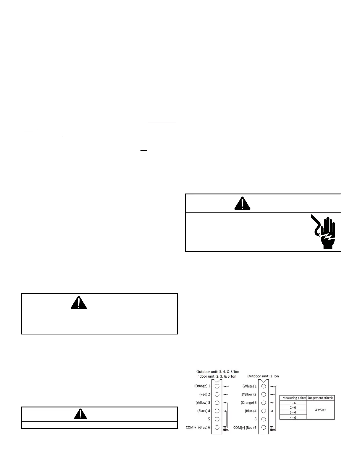
Testing EEV Coil Resistance
To check the resistance of the EEV coil, rst disconnect the
EEV cable from the Control Board. Read resistance be-
tween the connect pins, and then make sure the resistance
falls in the range of 40 to 50 Ω.


 To Next Page