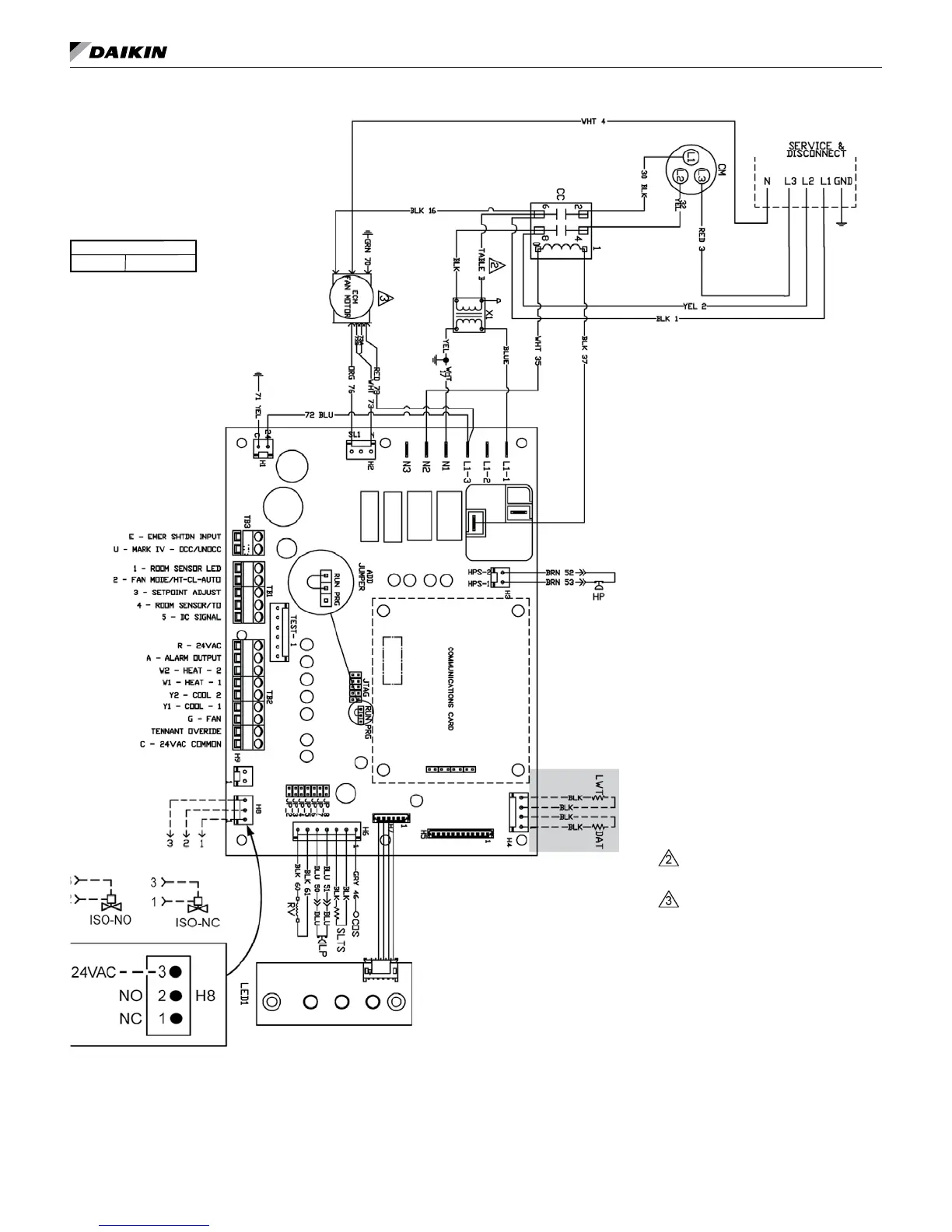
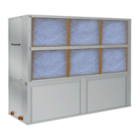
tyPiCal Wiring diagraMs
Figure 38: MicroTech III Unit Controller with EC Motor and Optional Communication Module – 460-60-3 Unit Sizes 024-070
Drawing No. 910102101
Wiring diagrams are typical. For the
latest drawing version refer to the wiring
diagram located on the inside of the
controls access panel of the unit.
Legend
Item Description
CC Compressor - Contactor
CM Compressor - Motor
COS CondensateOverowSensor
HP High Pressure Switch
ISO-NC Isolation Valve - Normally Closed
ISO-NO Isolation Valve - Normally Open
LED1 LED Annunciator / Harness
LP Low Pressure Switch
SLTS Suction Line Temp Sensor
LWT Leaving Water Temp Sensor
MIII MicroTech III Main Board
RAT Return Air Temp Sensor
RV Reversing Valve Solenoid
X1 Transformer
_____
Standard Unit Wiring
_ _ _ _
Optional Wiring (by others)
Table B
460V/N BLK/RED
Note: Gray tinted areas in the wiring diagram: Units with factory installed communication module include Discharge Air Temperature (DAT) and
Return Air Temperature (RAT) sensors shipped loose and are field installed. The Leaving Water Temperature (LWT) sensor is factory installed.
Entering Water Temperature (EWT) sensor is included with ECM and/or Secondary Electric Heat.
Notes:
1. Main board jumpers:
JP3 Geothermal
Transformer:
Unused wire to be capped.
3-phase service with a neutral is required
for ECM fan motor and 460 VAC
operation.
www.DaikinApplied.com 31 IM 1049-9