16 | Technical data
Installer reference guide
270
ERGA04~08EA + EHVH04+08SU18+23EA
Daikin Altherma 3 R F
4P629090-1A – 2021.11
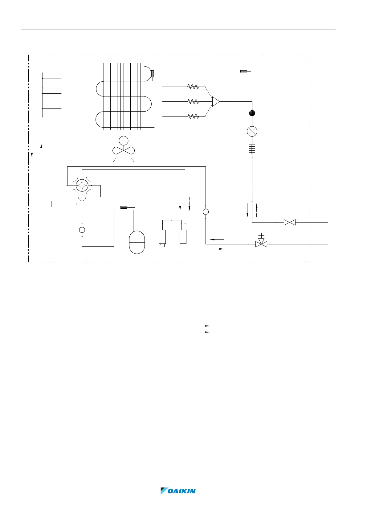
16.1 Piping diagram: Outdoor unit
R2T
7.0 CuT
7.0 CuT
7.0 CuT
7.0 CuT
7.0 CuT
7.0 CuT
12.7 CuT
12.7 CuT
12.7 CuT
6.4 CuT
6.4 CuT
6.4 CuT
6.4 CuT
4.0 CuT
4.0 CuT
9.5 CuT
15.9 CuT
3D110394
9.5 CuT
12.7 CuT
15.9 CuT
6.4 CuT
S1PH
Y1E
R1T
R3T
M1C
Y1S
4.0 CuT
M1F
b
ac
d
e
f
g
h
ij
k
k
g
g
a Field piping (liquid: Ø6.4mm flare connection) M1C Compressor
b Field piping (gas: Ø15.9mm flare connection) M1F Fan
c Stop valve (liquid) R1T Thermistor (outdoor air)
d Stop valve with service port (gas) R2T Thermistor (heat exchanger)
e Filter R3T Thermistor (compressor discharge)
f Muffler with filter S1PH High pressure switch (automatic reset)
g Capillary tube Y1E Electronic expansion valve
h Heat exchanger Y1S Solenoid valve (4‑way valve)(ON: cooling)
i Accumulator Heating
j Compressor accumulator Cooling
k Muffler
 Loading...