FTX-N/U, FVXS-N, FDMQ-R Series EDUS091558E
369
3P427537-1A
1. Remove the front panel, service lid, and front grille in accordance with the installation
manual for the air conditioner.
2. Install the HA PCB.
Installation procedures for the HA PCB differ by model type.
Refer to the relevant section.
G
G
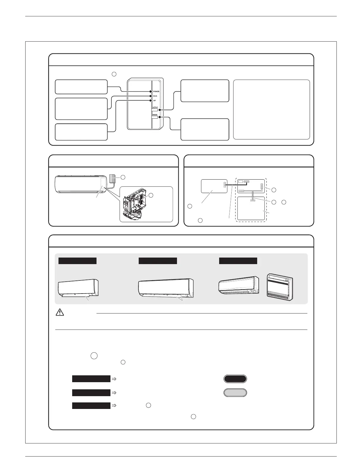
HA PCB Installation Procedure (1)
Names of Parts
Installation Position Wiring Outline
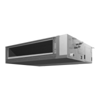
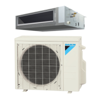
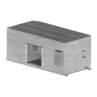
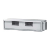
Type B model
0QVƂVVGFYKVJCP5EQPPGEVQT
ƃCRU
Type A model
0QVƂVVGFYKVJCP5EQPPGEVQT
ƃCR
Other models
(KVVGFYKVJCP5EQPPGEVQT
etc.
For Proceed to “HA PCB Installation Procedure (2) ”
Type A
Type A model
For Proceed to “HA PCB Installation Procedure (2) ”
Type B model Type B
For %QPPGEVVJGEQPPGEVKQPEQTFVQVJG5EQPPGEVQTKPCEEQTFCPEGYKVJVJG
installation manual for the air conditioner.
(It is not necessary to install the HA PCB.) After making the connection, return
the front grille, service lid, and front panel to their original positions.
Other models
D
G
Inside the indoor unit
S602
S21
S601
S403
Printed-circuit board
of the indoor unit
A
Wireless LAN
connection adapter
D
Connection cord
HA PCB
G
or Harness
H J
Wireless LAN connection
adapter
Electrical wiring box
HA PCB
G
A
Be sure to turn OFF the power at the time of installation work.
Touching any electric parts with the power turned ON may cause electric shock.
WARNING
ƃCR ƃCRU
AP lamp (yellow)
lights when connected directly
to a smartphone.
5'672DWVVQP
Use when connecting to a
router (wireless LAN
access point).
lights when connecting to a
router (wireless LAN access
point).
470NCORQTCPIG
219'4NCORITGGP
lights when running.
/1&'DWVVQP
Switches modes
(RUN/AP) when held
down.
Wireless LAN connection adapter
A
[Resetting the connection adapter]
r If the [SETUP] button and the [MODE]
button are held down together for 5
seconds, all lamps will begin blinking.
If the [SETUP] button is pressed in
this state, settings will revert to factory
default values.
(Data including network settings and
power consumption history are
erased.)
 Loading...