370
FTX-N/U, FVXS-N, FDMQ-R Series EDUS091558E
3P427537-1A
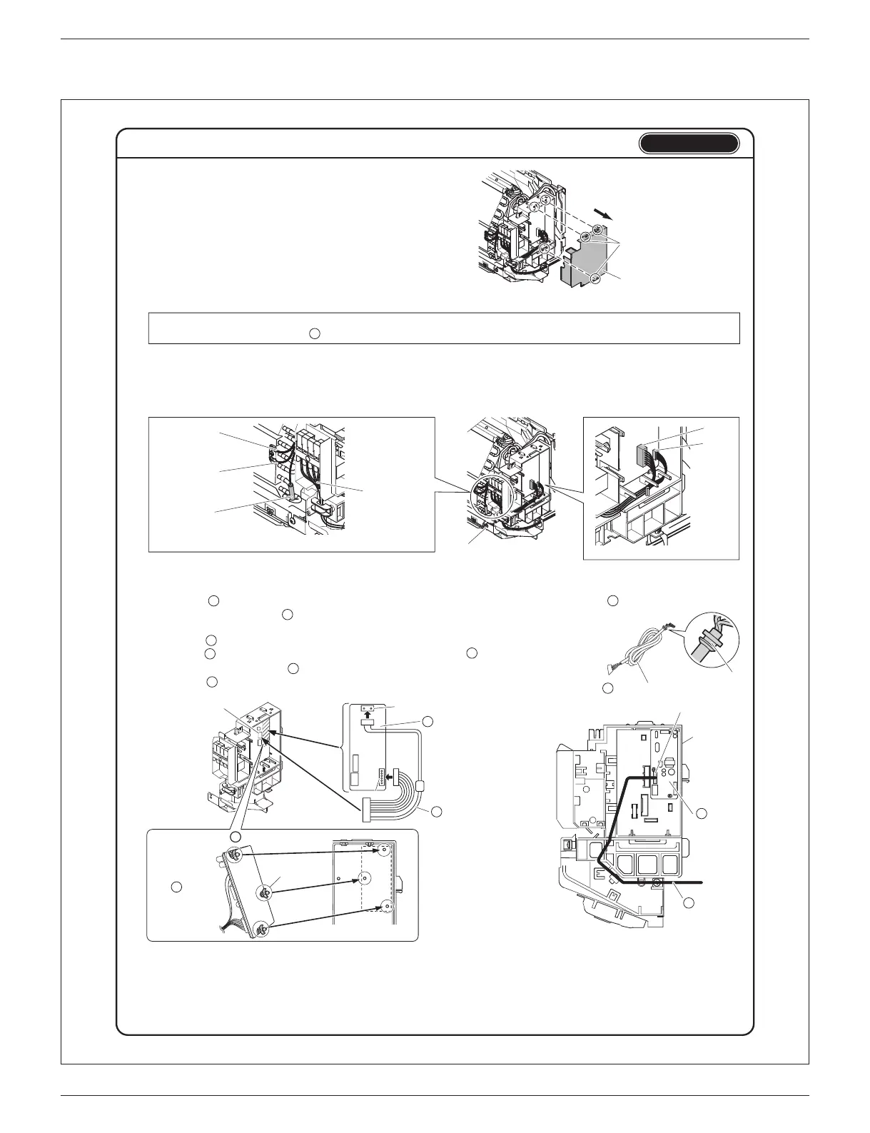
HA PCB Installation Procedure (2)
Type A
Electrical wiring box cover
Hooks
3. Remove the electrical wiring box cover.
r Disengage the hooks to remove the electrical wiring box cover.
Mounting screw of electrical
wiring box
S200
S6
* The position of the ground wire may differ depending on the model.
r
Make sure that the
mounting bracket of the
thermistor will not fall off.
Ground wire*
(Green/Yellow)
Ground wire*
(Green)
Inter-unit wire
Thermistor
4. Remove the electrical wiring box (if necessary).
1) Disconnect the inter-unit wire.
2) Disconnect the fan motor connector (S200) and swing motor connector (S6).
3) Disconnect the thermistor and ground wire from the heat exchanger (2 screws).
(Some models may not have ground wire.)
4) Remove the mounting screw of the electrical wiring box (1 screw).
If there is workspace on the right-hand side of the indoor unit, the installation work can be conducted without removing the
electrical wiring box. Connect the HA PCB without removing the electrical wiring box, if possible.
G
5. Install the HA PCB to the electrical wiring box.
1) Attach the harness (with ferrite core), by connecting it to the S601 and S602 connectors on the HA PCB. (See Fig. 2)
2) Insert the connector of the harness (with ferrite core) into the S403 connector
on the electrical wiring box. (See Fig. 2)
3) Install the HA PCB to the electrical wiring box. (See Fig. 2)
4) Insert the connection cord into the S21 connector (white) on the HA PCB. (See Fig. 3)
r Insert the connector of the connection cord without the cord anchor. (See Fig. 1)
5) 4QWVGVJGEQPPGEVKQPEQTFCUUJQYPKPVJGƂIWTG5GGFig. 3)
H
G
H
D
D
D
G
G
D
Cord anchor
Connection cord
Fig. 1
Fig. 3
S403
S21 connector (white)
G
HA PCB
To S403
connector
HA PCB
G
Fig. 2
D
Connection
cord
Harness
(with ferrite core)
H
S602
S601
Spacer
Electrical wiring box
Electrical
wiring box
Back of the
HA PCB
G
How to attach the HA PCB
G
6. Return the electrical wiring box cover and electrical wiring box (if it was removed) to their
original positions.
7. Return the front grille, service lid, and front panel to their original positions in accordance
with the installation manual for the air conditioner.
 Loading...