6 | Unit installation
Installer reference guide
28
FTXP20~35N5V1B + ATXP20~35N5V1B
Split system air conditioners
4P519439-20U – 2022.09
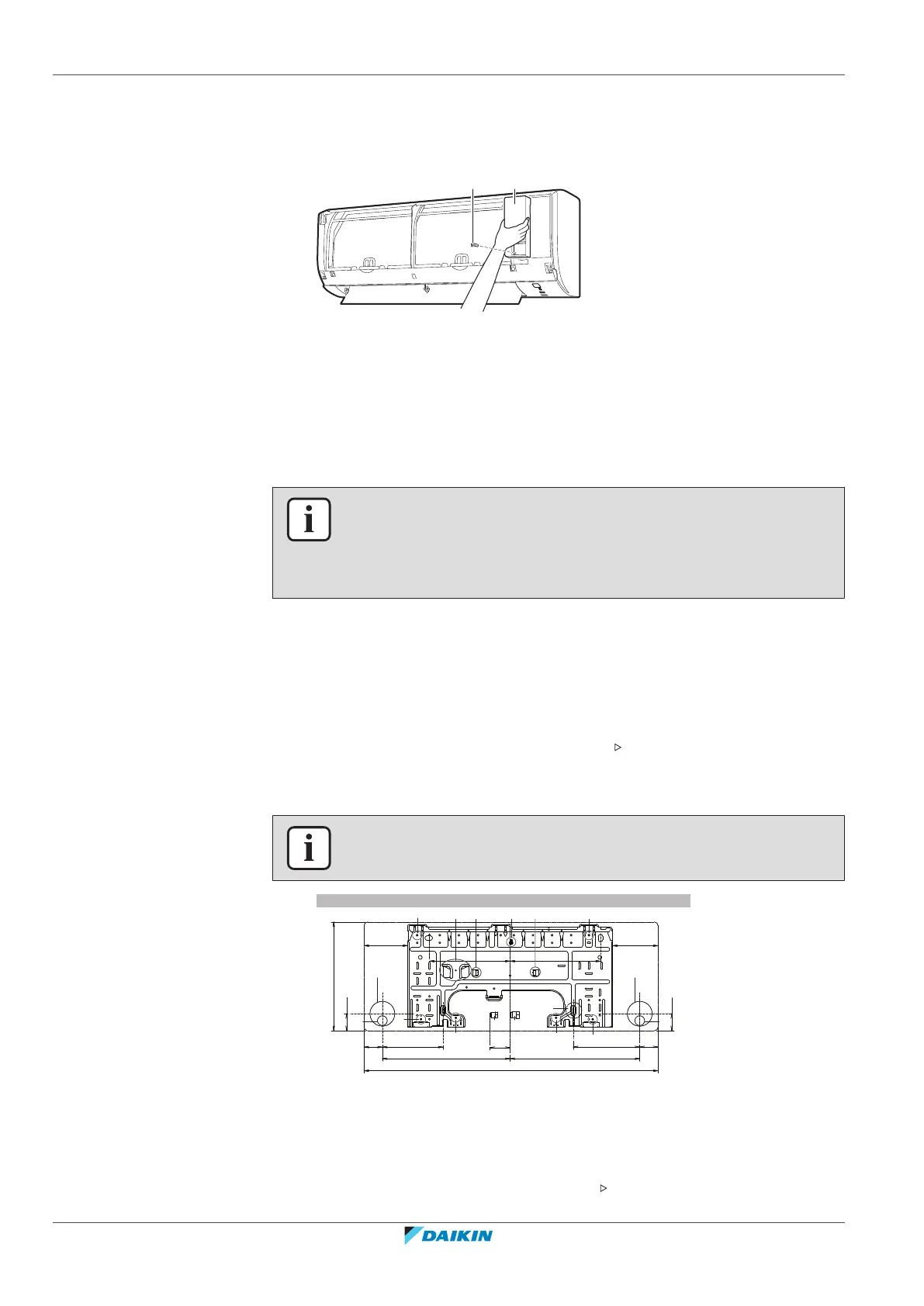
6.2.6 To open the service cover
1 Remove 1 screw from the service cover.
2 Pull out the service cover horizontally away from the unit.
a Service cover screw
b Service cover
6.3 Installing the indoor unit
6.3.1 Precautions when installing the indoor unit
INFORMATION
Also read the precautions and requirements in the following chapters:
▪ General safety precautions
▪ Preparation
6.3.2 To install the mounting plate
1 Install the mounting plate temporarily.
2 Level the mounting plate.
3 Mark the centres of the drilling points on the wall using a tape measure.
Position the end of tape measure at symbol " ".
4 Finish the installation by securing the mounting plate on the wall using
M4×25L screws (field supply).
INFORMATION
The removed pipe port cover can be kept in the mounting plate pocket.
337
770
A
285
44.5
170
48
48
44.5
116.5
117
337
50
213 237
170
A
d
e
(mm)
a
a
f
h g
a
a
b
a
c
a
c
a
d
e
A
A Mounting plate for class 20~35
a Recommended mounting plate fixing spots
b Pocket for the pipe port cover
c Tabs for placing a spirit level
d Through-the-wall hole Ø65 mm
e Drain hose position
f Position for the tape measure at symbol " "
g Gas pipe end
 Loading...