ESIE17-19C |
Page 6 19/08/19 | Version 1.1
Optimized Heating 4
Figure 3-1: 1 service port at the stop valves ............................................................................................................ 66
Figure 3-2: 3 service ports at the stop valves .......................................................................................................... 67
Figure 3-3: Removing the front panel ....................................................................................................................... 70
Figure 3-4: Replacing the streamer unit ................................................................................................................... 71
Figure 3-5: Removing the humidity sensor PCB assembly ...................................................................................... 72
Figure 3-6: Installing the humidity sensor PCB assembly ........................................................................................ 72
Figure 3-7: Removing plate work ............................................................................................................................. 74
Figure 3-8: Removing the screw .............................................................................................................................. 74
Figure 3-9: Removing casing of the sensor ............................................................................................................. 75
Figure 3-10: Removing PCB connectors .................................................................................................................. 75
Figure 3-11: Removing refrigerant connection cover ............................................................................................... 76
Figure 3-12: Removing the top plate ........................................................................................................................ 77
Figure 3-13: Removing the front plate ...................................................................................................................... 77
Figure 3-14: Removing the compressor sound insulation ........................................................................................ 78
Figure 3-15: Removing the switch box ..................................................................................................................... 80
Figure 3-16: Removing the 4-way valve ................................................................................................................... 81
Figure 3-17: Removing the 4-way valve coil ............................................................................................................ 83
Figure 3-18: Removing the compressor ................................................................................................................... 85
Figure 3-19: Removing the DC fan motor assembly ................................................................................................ 88
Figure 3-20: Removing the expansion valve ............................................................................................................ 89
Figure 3-21: Removing the expansion valve motor .................................................................................................. 91
Figure 3-22: Locking the expansion valve motor ..................................................................................................... 92
Figure 3-23: Locking the expansion valve motor ..................................................................................................... 93
Figure 3-24: Removing the high pressure switch ..................................................................................................... 94
Figure 3-25: Remove screws main PCB .................................................................................................................. 95
Figure 3-26: Remove wiring from terminals ............................................................................................................. 95
Figure 3-27: Apply heat conductive paste ................................................................................................................ 96
Figure 3-28: Removing the propeller fan blade assembly ........................................................................................ 97
Figure 5-1: How to change power saving mode OFF to ON - Remote controller: ARC466A33/ARC466A55 ........ 106
Figure 5-2: How to change power saving mode OFF to ON - Remote controller: ARC480A11 ............................. 107
Figure 5-3: How to change fan OFF to ON when in cooling thermo off - Remote controller: ARC466A33/ARC466A55
108
Figure 5-4: How to change fan OFF to ON when in cooling thermo off - Remote controller: ARC480A11 ............ 108
Figure 5-5: How to adjust target set temperature in heating operation - Remote controller: ARC466A55 ............. 109
Figure 5-6: How to adjust target set temperature in heating operation - Remote controller: ARC480A11 ............. 110
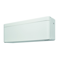
Figure 5-7: FTXTA-AW .......................................................................................................................................... 112
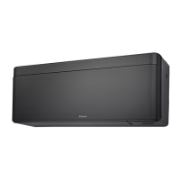
Figure 5-8: FTXTM30-M ......................................................................................................................................... 112
Figure 5-9: FTXTM40-M ......................................................................................................................................... 113
Figure 5-10: FTXTP-K, ATXTP-K ........................................................................................................................... 113
Figure 5-11: FVXM-F ............................................................................................................................................. 113
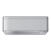
Figure 5-12: RXTA-N, RXTM-N, RXTP-N, RXTP-N9, ARXTP-N ........................................................................... 114
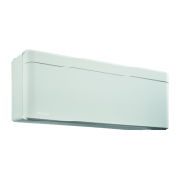
Figure 5-13: FTXTA-AW ........................................................................................................................................ 115
Figure 5-14: FTXTM40-M ....................................................................................................................................... 116
Figure 5-15: FTXTM-M, FTXTP-K, ATXTP-K ......................................................................................................... 116