ESIE17-19C | Part 3. Repair 3.3. Unit specific repair procedures
19/08/19 | Version 1.1 Page 75
Optimized Heating 4
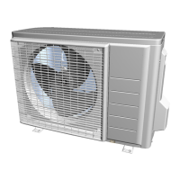
Figure 3-9: Removing casing of the sensor
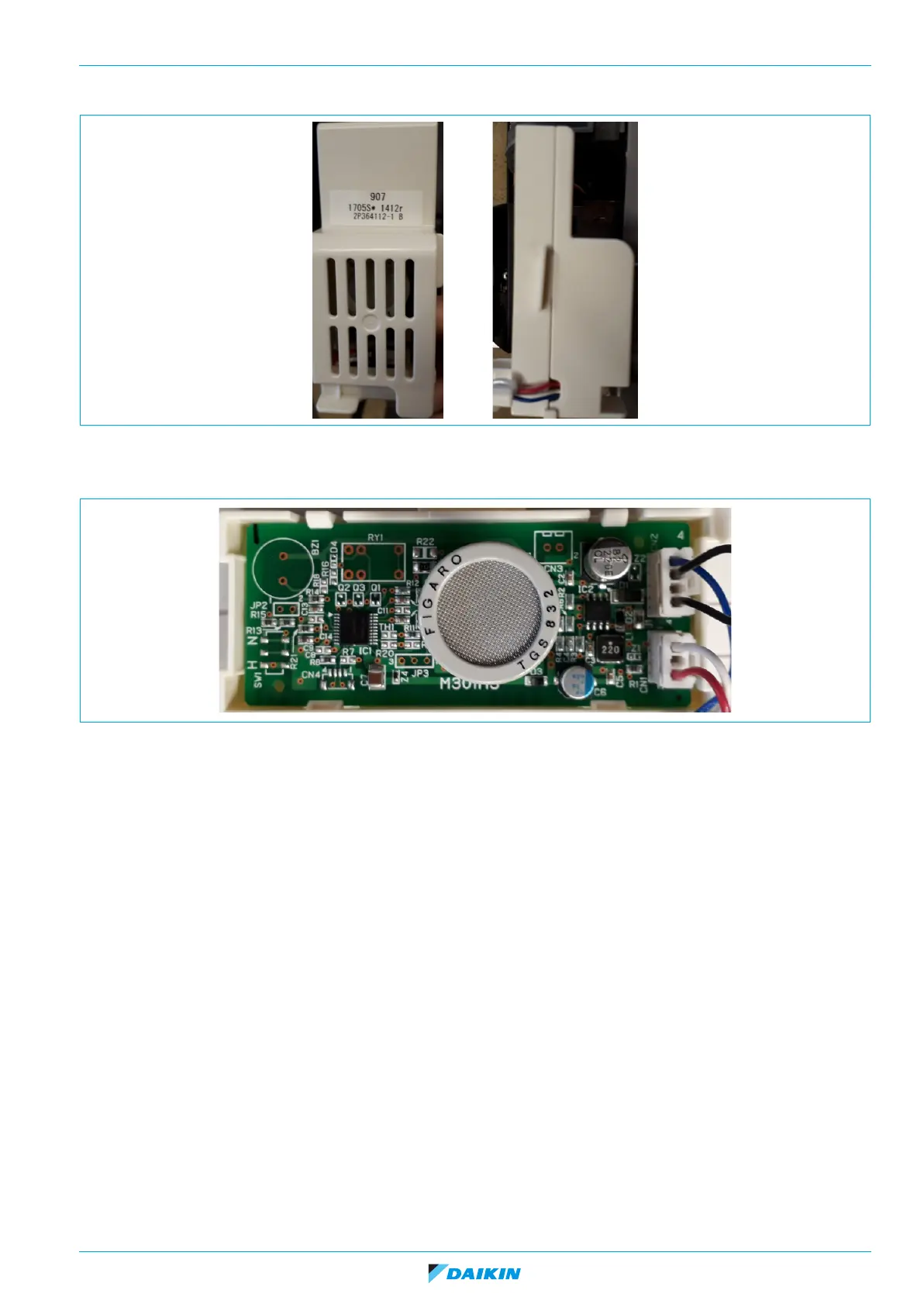
4. Remove PCB connectors, put new PCB in casing.
Figure 3-10: Removing PCB connectors
Installation
1. Proceed in reverse order.