FWPC
TECHNICAL MANUAL14
9 ELECTRICAL CONNECTIONS
Make the electrical connections with the power supply discon-
nected, in accordance with current safety regulations.
All the wiring must be done by qualied personnel.
For each thermal ventilating unit provide a main circuit
breaker (IL), with opening contacts separated by at least 3
mm and an adequate protection fuse (F).
Electrical intakes are shown on the rating labels on the units.
During installation, strictly abide by the indications on the wir-
ing diagram for the unit-control panel combination.
NOTE: The electric wires (power and control circuits) must be
pulled in through the gland on the side of the electric box
where the plumbing connections are located and then con-
nected to the terminals.
WARNING: COMMON motor wire = WHITE, wrong connec-
tion may cause serious damages to the motor.
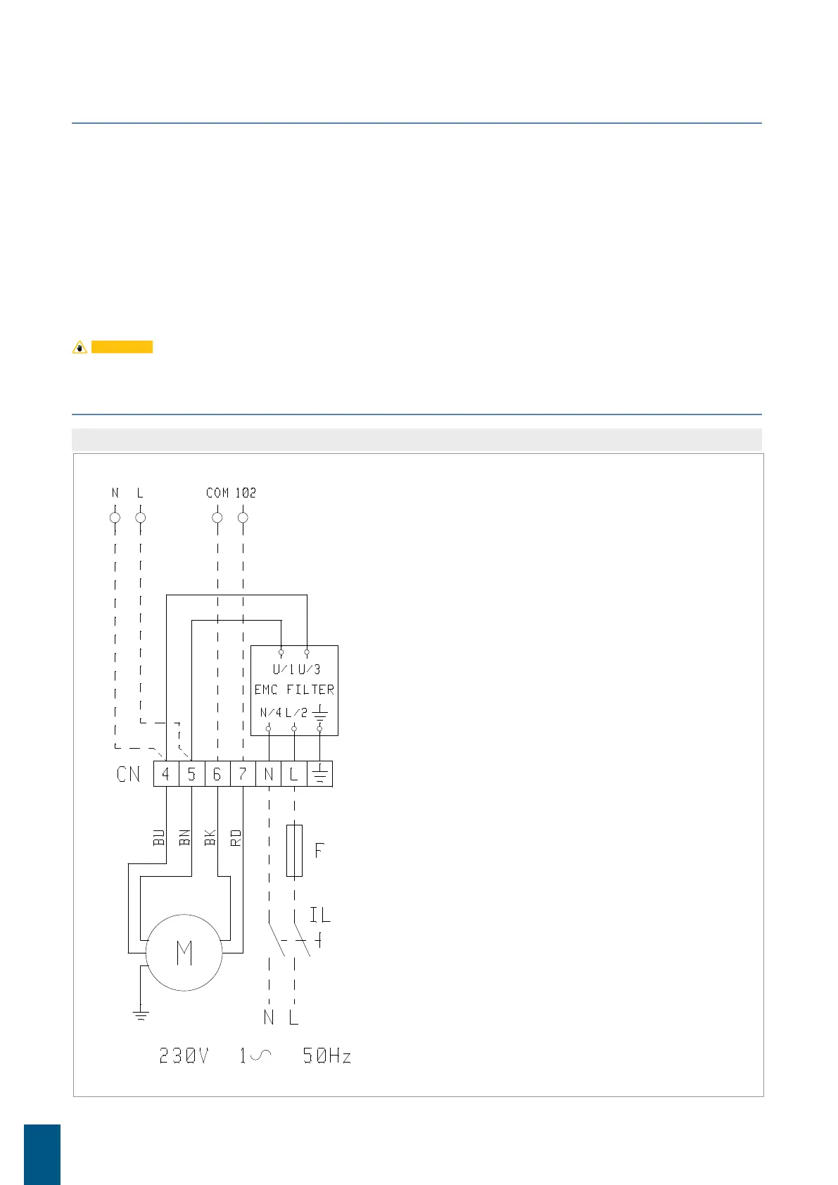
10 ELECTRICAL WIRES
» General wiring diagram
Electrical wiring diagram
legend:
L Phase
N Neutral
CN Terminal board connector
F Fuse (not supplied)
IL Circuit breaker (not
supplied)
... Wirings made by supplier
M Fan motor