7 | Unit installation
Installer reference guide
31
EKHWET90~120BAV3
R32 Split series – Domestic hot water tank
4P680077-1 – 2021.11
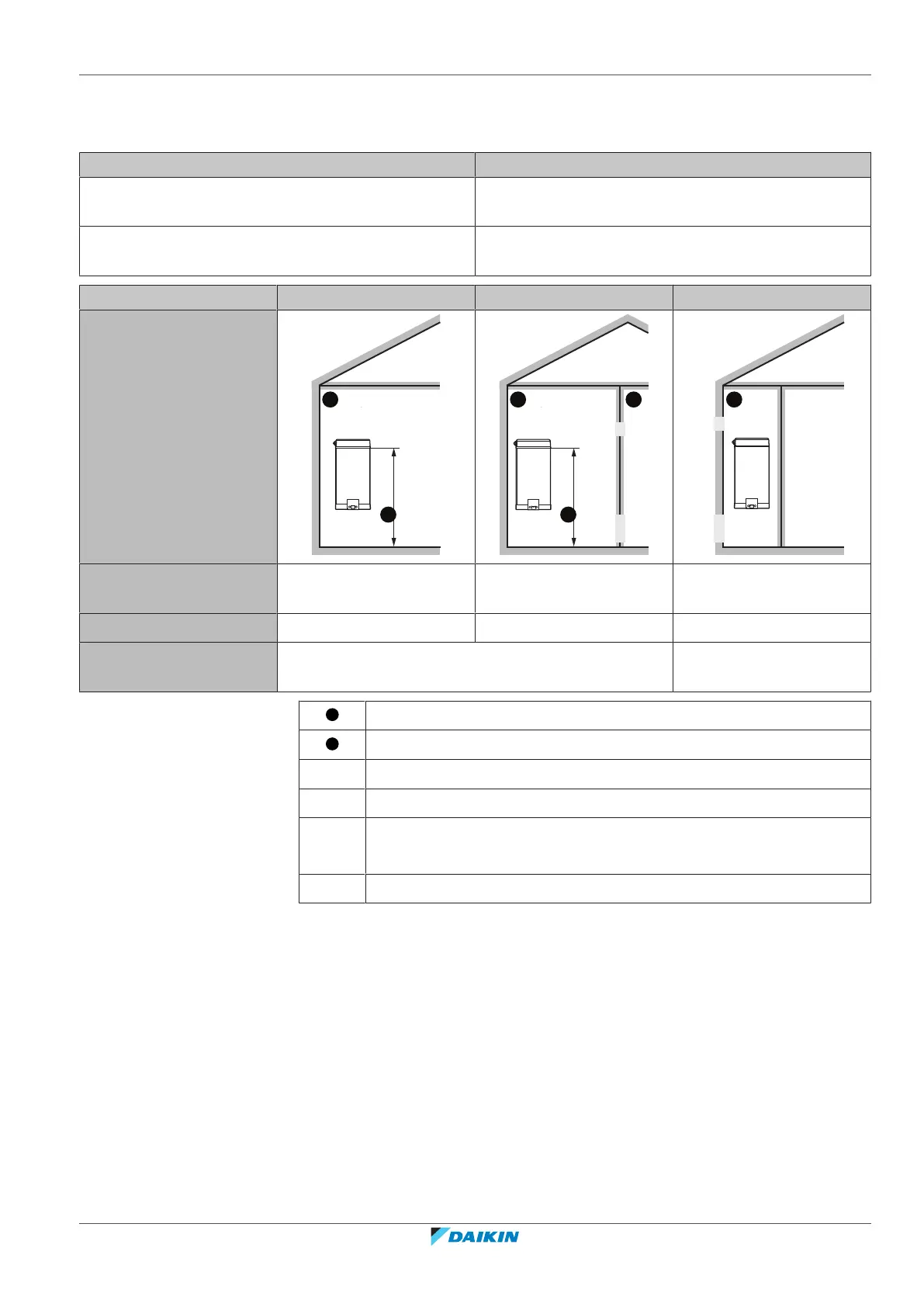
7.1.3 Installation patterns
Depending on the type of room in which you install the indoor unit, different installation patterns are allowed:
Room type Allowed patterns
Living room, kitchen, garage, attic, basement, storage
room
1, 2
Technical room (i.e. room that is NEVER occupied by
persons)
1, 2, 3
PATTERN 1 PATTERN 2 PATTERN 3
Ventilation openings N/A Between room A and B Between room A and
outside
Minimum floor area Room A Room A + Room B N/A
Restrictions See "PATTERN 1"[432], "PATTERN 2"[432], and
"Tables for PATTERN 1 and 2"[433]
See "PATTERN 3"[435]
Room A (= room where indoor unit is installed)
Room B (= adjacent room)
c1 Bottom opening for natural ventilation
c2 Top opening for natural ventilation
H
release
Actual release height:
From floor to 100 mm below top of the unit.
N/A Not applicable
Minimum floor area / Release height:
▪ The minimum floor area requirements depend on the release height of the
refrigerant in case of a leakage. The higher the release height, the lower the
minimum floor area requirements.
▪ The default point of release is 100 mm below the top of the unit.
▪ You can also take advantage of the floor area of the adjacent room (= room B) by
providing ventilation openings between the two rooms.
▪ For installations in technical rooms (i.e. room that is NEVER occupied by
persons), additionally to patterns 1 and 2, you can also use PATTERN3. For this
pattern there are no requirements to the minimum floor area if you provide 2
openings (one at the bottom, one at the top) between the room and the outside
to ensure natural ventilation. The room must be protected from frost.