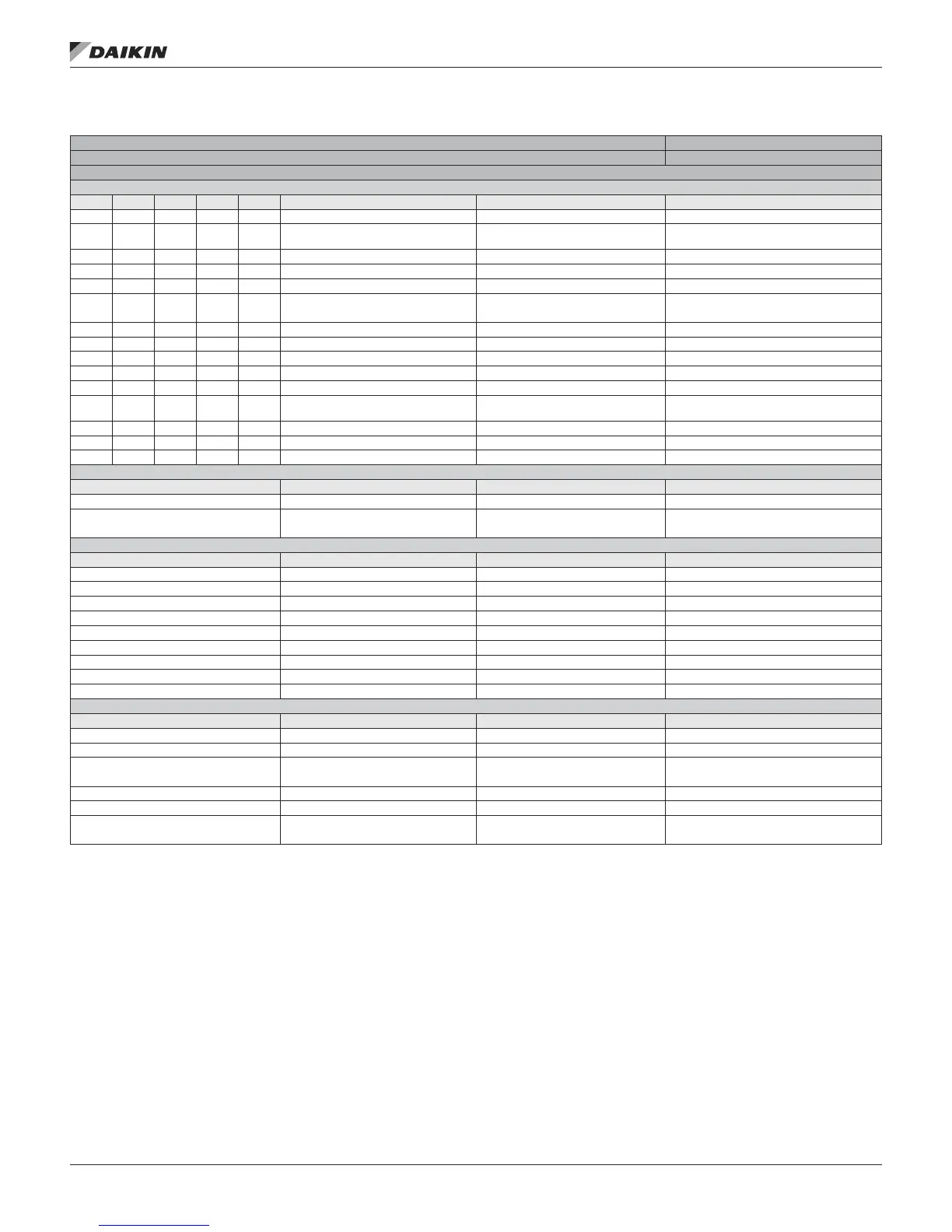
Table 8: RTU/MPS/DPS/DPH Expansion Module B I/O
I/O Cong. Code Condition
RTU, MPS & DPS – Expansion Module B Pos. 1=0,2,3o4
Heating, F&BP Dampers, MPS Dehumidication, MPS/DPS Energy Recovery, MPS Staged Exhaust Fan
Universal Inputs/Outputs
# DI AI DO AO Point Comments Cong. Code Condition
X 1 X FSG Ign_Pilot Input (FSG-8) Dry Contact 1 = 0 & 10 = 4
X 1 X Ent Fan & Lvg Coil T
10K Thermistor (STD) — Gas or
Electric Heat & Dehum
(1 = 2) & (19 = 1)
X 2 X Gas Heat LS1 Switch Dry Contact 1 = 0 & 10 = 4
X 2 X Reheat #1 0–10 VDC 1 = 2 & 28 = 2
X 3 X Gas Heat LS2 Switch Dry Contact 1 = 0 & 10 = 4
X 3 X OA Flow 0–10 VDC or 4–20 mA
1 = 2, 3 or 4 & 8 = 1, 2, 3, 5, 6 or 7 & 9 = 6
& 30 ≠ 3, 4, 5 or 6
X 4 X FSG Alarm Input (FSG-3) 1=0 & (10=3 or 10=4)
X 4 X Supply Temp Leaving Wheel 10K Thermistor (STD) 1 = 2, 3 or 4 & 20 > 0 & 30 ≠ 3, 4, 5 or 6
X 5 X Exhaust Temp Leaving Wheel 10K Thermistor (STD) 1 = 2, 3 or 4 & 20 > 0 & 30 ≠ 3, 4, 5 or 6
X5 X Duct Static Pressure 1 4–20 mA 1 = 0 & 15 = 6
X 6 X Relative Humidity 0–10 VDC or 4–20 mA 1 = 2
X 7 X Heating Valve 2–10 VDC
1 = 0, 1 or 2 & 10 = 1, 10 = 3, 10 = 4, 10 =
5, 10 = 7 or 10 = 8
X 7 X SCR 0–10 VDC 1 = 0, 1 or 2 & 10 = 6
X 8 X F & BP Damper 0–10 VDC 1 = 0 or 1 & 3 = 3 or 10 = 1
X8 X Constant Speed Enthalpy Wheel Energy Recovery 1 = 2 & 20 =1 or 6
Digital Input — 115V-230V
# Point Comments Cong. Code Condition
DI OAD End Switch Input 115 VAC Input 1 = 2 & 8 = 8 or 9
DI Freezestat Switch 115 VAC Input
1 = 3 or 4 & 10 = 5 & 8 = 8 or 9 &
30 ≠ 3, 4, 5 or 6
Digital Outputs — Relay (SPST, Normally Open, 230 VAC 3 Amp)
# Point Comments Cong. Code Condition
DO 1 Gas Heat (ON/OFF) 1 = 0 or 2 10 =3 , 4, 7 or 8
DO 1 Heat Stage 1 1 = 0, 1 or 2 & 10 = 2
DO 1 SCR Enable 1 1 = 0, 1 or 2 & 10 = 6
DO 1 Constant Speed Enthalpy Wheel Energy Recovery 1 = 3 or 4 & 20 = 1 or 6 & 30 = 1 or 2
DO 2 Pilot Gas (ON/OFF) 10 = 4
DO 2 Heat Stage 2 1 = 0, 1 or 2 & 10 = 2 & 11 > 1
DO 2 SCR Enable 2 1 = 0, 1 or 2 & 10 = 6
DO 3 Heat Stage 3 1 = 0, 1 or 2 & [10 = 8 or 10 = 2 & 11 > 2]
DO 4 Heat Stage 4 1 = 0, 1 or 2 & [10 = 8 or 10 = 2 & 11 > 3]
Digital Outputs — Triac (24 VAC, .5 Amp)
# Point Comments Cong. Code Condition
DO 5 Heat Stage 5 1 = 0, 1 or 2 & 1 = 0 & 10 = 2 & 11 > 4
DO 5 Exh Fan Stage 1 1 = 2 & 16 = C, D or E
DO 5 Bypass Damper CLOSED Energy Recovery
1 = 2, 3 or 4 & 20 > 0 & 8 = 3 or 6 &
30 ≠ 3, 4, 5 or 6
DO 6 Heat Stage 6 1 = 0 & 10 = 2 & 11 > 5
DO 6 Exh Fan Stage 2 1 = 2 & 16 = D or E
DO 6 Bypass Damper OPEN Energy Recovery
1 = 2, 3 or 4 & 20 > 0 & 8 = 3 or 6 &
30 ≠ 3, 4, 5 or 6
IM 919-3 • MICROTECH III CONTROLLER 18 www.DaikinApplied.com
ConTroller InpuTs/ouTpuTs