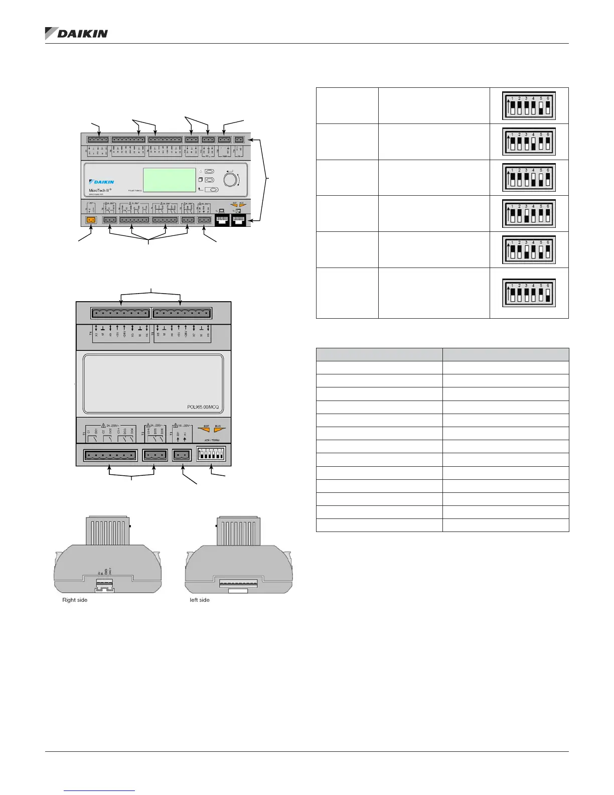
Main Control Board (MCB)
Figure 1: Main Control Board
Figure 2: Expansion Boards A, B, C, D, E
Figure 3: Expansion Board Side Views
Figure 4: Dip Switch Settings
Expansion
Board A
Switch #5 in the up
position (all others down)
Expansion
Board B
Switch #4 in the up
position (all others down)
Expansion
Board C
Switch #4 and #5 in the
up position (all others
down)
Expansion
Board D
Switch #3 in the up
position (all others down)
Expansion
Board E
Switch #3 and #5 in the
up position (all others
down)
Dipswitch #6
Switch #6 must be in the
up position on the last
expansion board in the
string regardless whether
it is A, B, C, D, or E.
Table 2: MCB I/O Connection Labeling
MCB I/O Connection Label
T1 24 VOLT POWER SUPPLY
T2 DIGITAL OUTPUT 1,
T3 DIGITAL OUTPUT 2, 3, 4
T4 DIGITAL OUTPUT 5, 6, 7, 8
T5 DIGITAL OUTPUT 9, 10
T6 DIGITAL INPUT 5, 6
T7 ANALOG INPUT 1, 2, 3
T8 UNIVERSAL I/O 1, 2, 3, 4
T9 UNIVERSAL I/O 5, 6, 7, 8
T10 DIGITAL INPUT 1, 2
T11 DIGITAL INPUT 3, 4
T12 MODBUS/VFD
T13 PROCESS BUS/FUTURE
Internal Modbus
Digital Inputs
Universal I/O
Analog Inputs
Remote
Keypad/
Display
Digital Inputs
Digital Outputs
Power
Supply
Universal I/O
Dip Switches
Digital Input
Digital Output
IM 919-3 • MICROTECH III CONTROLLER 4 www.DaikinApplied.com
InTroduCTIon