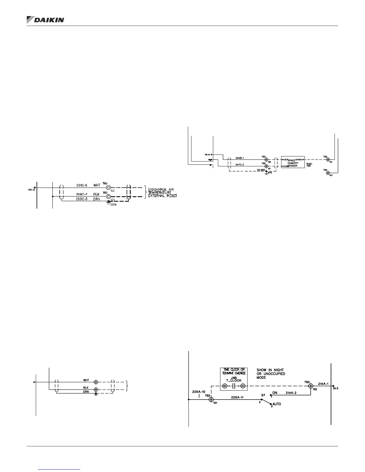
External Discharge Air Reset Signal
The discharge air temperature set point on DAC units can be
reset by an external voltage or current signal applied to analog
input MCB-AIX4. The external reset method can be selected at
the controller keypad. External reset requires a eld supplied
reset signal in the range of 010 VDC, 2-10 VDC, 0-20 mA, or
4-20 mA wired to terminals 132 and 133 on the eld terminal
block (TB2). Refer to the unit wiring diagrams or typical wiring
diagrams on page 44 for wiring termination details. If the
external reset option is selected, the controller linearly resets
the cooling and heating discharge air temperature set points
between user-programmed minimum and maximum values
as the eld supplied reset signal varies from a minimum to
maximum (or maximum to minimum) value.
The external reset signal must be eld-wired to the unit using a
twisted pair, shielded cable (Belden 8761 or equivalent). Cable
with 22 AWG conductors is sufcient.
Figure 22: External Discharge Air Reset Signal Wiring
Diagram
External Outdoor Air Damper Reset Signal
On units equipped with a 0-100% modulating economizer the
minimum outside air damper position set point can be reset
by an external voltage or current signal. The external reset
method can be selected with the Min OA Reset parameter
in the Min OA Damper menu in the Standard Menus via
the controller keypad/display. External reset requires a eld
supplied reset signal in the range of 0-10 VDC or 0-20 mA
wired to terminals 124 and 125 on the eld terminal block
(TB2). Refer to the unit wiring diagrams for wiring termination
details. If the external reset option is selected, the controller
linearly resets the outside air damper position set point
between user-programmed minimum (Demand Control
Ventilation Limit) and maximum (Ventilation Limit) values as
the eld supplied reset signal varies between a minimum
and maximum (or maximum to minimum) value. The external
reset signal must be eld-wired to the unit using a twisted pair,
shielded cable (Belden 8761 or equivalent). Cable with 22
AWG conductors is sufcient.
Figure 23: External Outdoor Air Damper Reset Signal
Wiring Diagram
Humidity Sensors
Either a wall mount or duct mount Humidity sensor is available.
The sensor must be wired to terminals 126, 127 and 131
on the unit eld terminal block (TB2). Terminal 126 is wired
to OUT, terminal 127 to COM and terminal 131 to IN on the
humidity sensor. These terminals are factory wired to the
Expansion Board A AIX6. The sensor can deliver 0-10VDC or
0- 20mA, the type of signal (VDC or mA) and the 0% and 100%
RH values are adjustable via the Dehum Setup menu in the
Commission Unit section on the keypad/display.
Figure 24: Humidity Sensor Wiring Diagram
Field Digital Input Signals
The following inputs may be available for eld connections to a
suitable device.
External Time Clock or Tenant Override
There are several methods of switching the rooftop unit
between occupied and unoccupied operation. It can be done
by the controller internal schedule, a network schedule, an
external time clock, or a tenant override switch.
If the internal schedule or a network schedule is used, eld
wiring is not required.
An external time clock or a tenant override switch can be used
by installing a set of dry contacts across terminals 101 and 102
on the eld terminal block (TB2). When these contacts close,
24 VAC is applied to binary input MCB-DI3, overriding any
internal or network schedule and placing the unit into occupied
operation (provided the unit is not manually disabled). When
the contacts open (24 VAC is removed from MCB-DI3) the
unit acts according to the controller internal time schedule or a
network schedule. Refer to the unit wiring diagrams for specic
wiring termination details.
Figure 25: Time Clock/Tenant Override Wiring Diagram
234C-5
124
TB2
TB2
125
125G
229C-6
235D-5
I
REMOTE ECONO. MIN. POSITIO
OR
EXTERNAL CO
2
MIN. CONTROL
IM 919-3 • MICROTECH III CONTROLLER 28 www.DaikinApplied.com
fIeld wIrIng